

Method and electronic device for forming beam in wireless communication system
a wireless communication system and wireless communication technology, applied in the field of electronic devices and methods for efficiently forming beams in wireless communication systems, can solve the problems of significant path loss of radio waves, limited electronic devices, and electronic devices having difficulty in forming optimal beam pair links
- Summary
- Abstract
- Description
- Claims
- Application Information
AI Technical Summary
Benefits of technology
Problems solved by technology
Method used
Image

Examples
Embodiment Construction
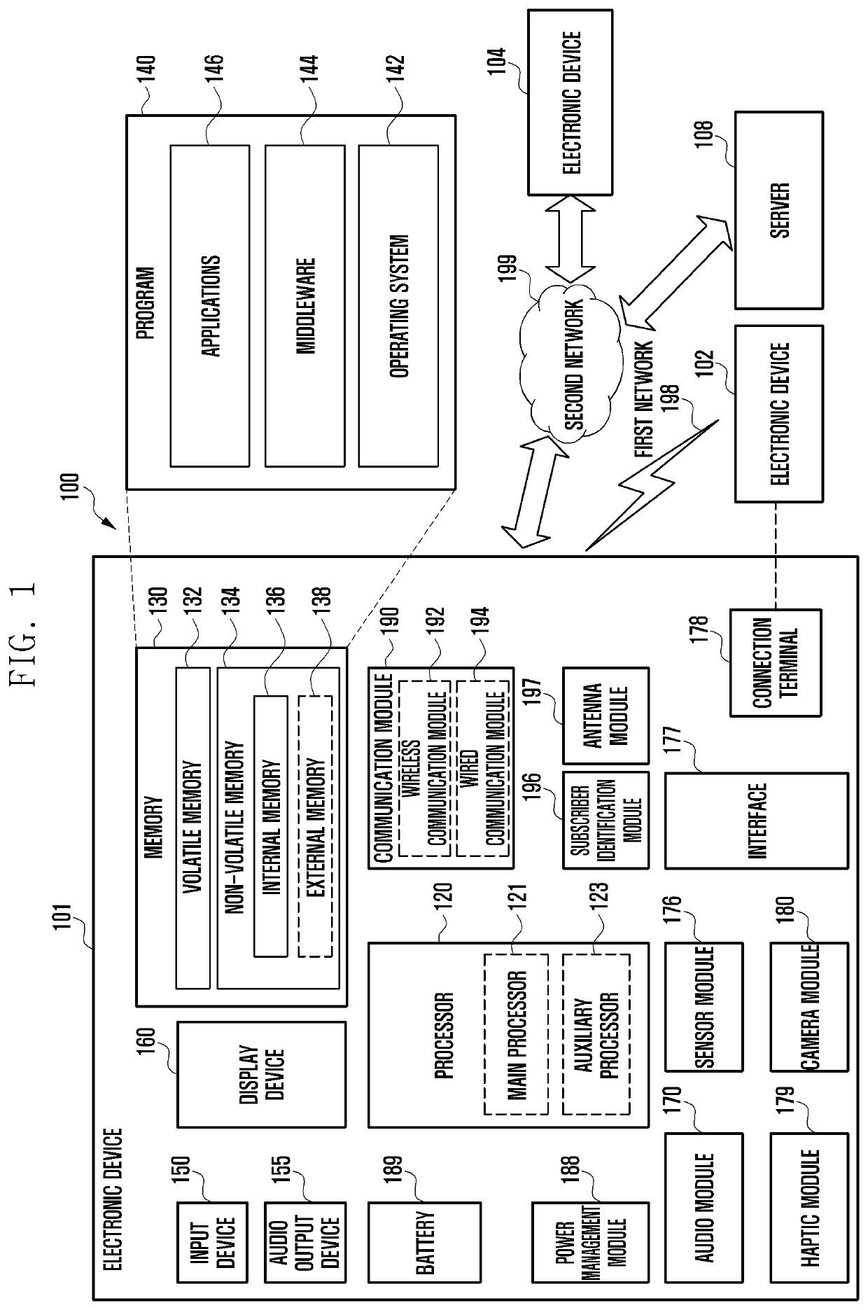
[0021]Various embodiments of the disclosure are described with reference to the accompanying drawings. However, various embodiments of the present disclosure are not limited to particular embodiments, and it should be understood that modifications, equivalents, and / or alternatives of the embodiments described herein can be variously made. With regard to description of drawings, similar components may be marked by similar reference numerals.
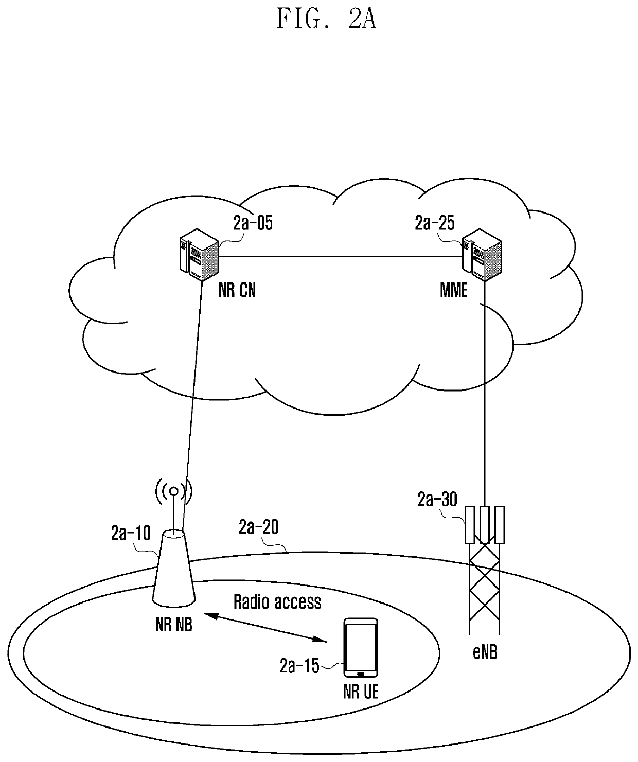
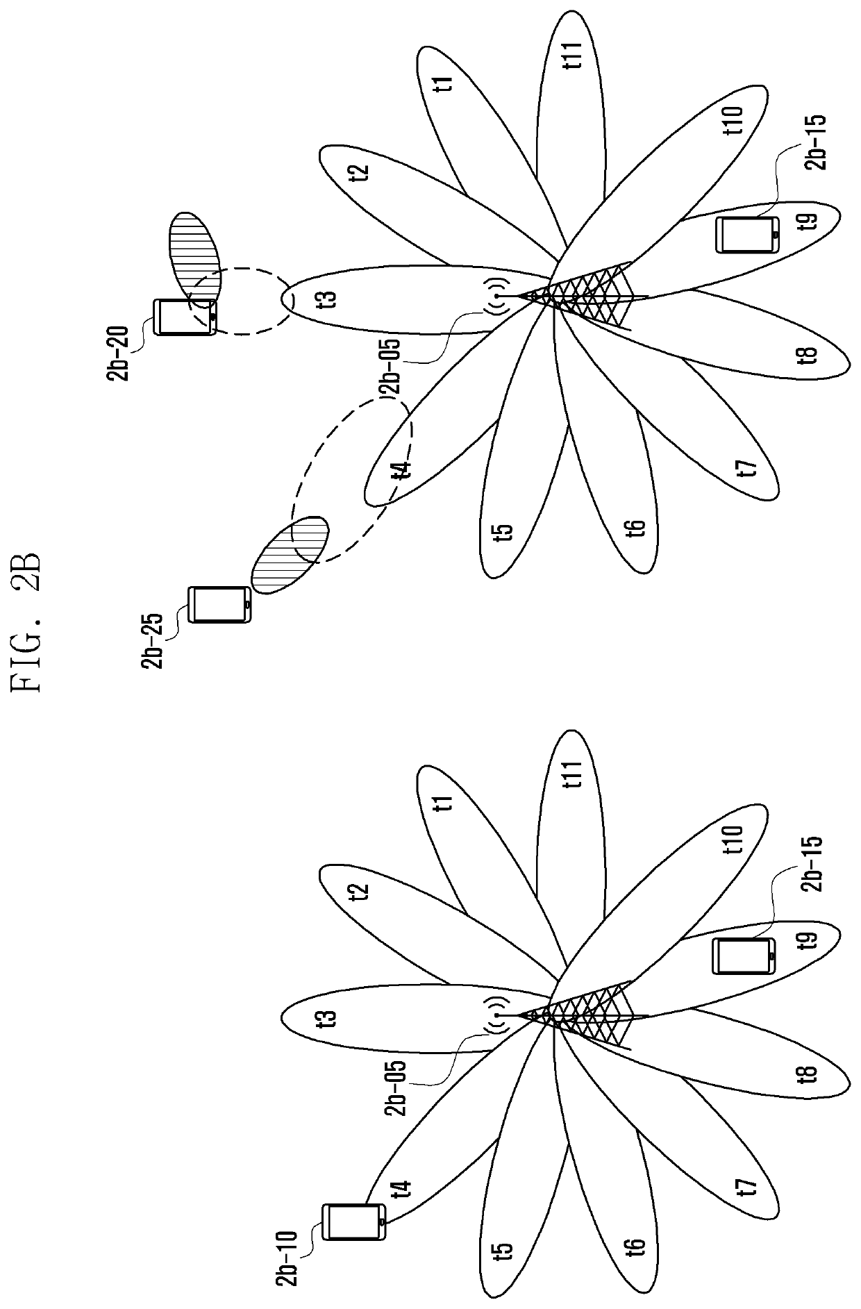
[0022]According to various embodiments of the present disclosure, it is possible to determine the optimal beam for wireless communication based on an identified communication state of an electronic device. In addition, the electronic device can determine the optimal beam in the current communication state and also form a beam pair link corresponding to the determined beam. Particularly, in wireless communication of a high frequency band, the electronic device can search for and determine the optimum beam and thereby efficiently perform wireless co...
PUM
 Abstract
Description
Claims
Application Information