Tape Dispenser System

a dispenser and tape technology, applied in the field of tape dispensers, can solve the problems of unnecessarily increasing the cost of manufacture and assembly of these devices, difficulty amplifying, and difficulty, and achieve the effect of efficient and cost-effective system

Inactive Publication Date: 2014-06-12
YARRISH JOHN JOSEPH +2
View PDF9 Cites 0 Cited by
  • Summary
  • Abstract
  • Description
  • Claims
  • Application Information

AI Technical Summary

Benefits of technology

[0007]One example of the present invention is a tape dispenser that provides an efficient and cost effective system and method of using the same for dispensing and cutting tape with a relatively straight pull by the user.
[0009]The tape dispenser may include one or more finger grips, e.g., formed on a portion of the inner wall, and a recessed thumb positioner, e.g., formed on a portion of the outer wall, for ergonomic and comfortable handling by the user.
[0011]The tape dispenser may also provide for easy location of the end of the tape. The tape dispenser allowing the tape to “stand up” (e.g., the free end of the tape does not adhere to any structure or surface of the system) after being cut or allowing it to “lie down” and stick to an anvil for future use. The anvil feature may be configured so as to be shorter in length than the width of the tape in order to facilitate easy access to the side of the end of the tape by the user.

Problems solved by technology

Linearly arranged cutting edges can be difficult to use as they require that the tape be pulled at an angle to the cutting edge.
A difficulty amplified when the cutting edge is not in an optimum position because the gap between the tape and the cutting edge increases, e.g., as the tape roll is depleted.
This complexity adds unnecessarily to the cost of manufacture and assembly of these devices.

Method used


Image

  • Tape Dispenser System
  • Tape Dispenser System
  • Tape Dispenser System

Examples


Embodiment Construction

[0021]The following detailed description and appended drawings describe and illustrate an exemplary embodiment of the invention. The description and drawings serve to enable one skilled in the art to make and use the invention, and are not intended to limit the scope of the invention in any manner.

[0022]It should be noted that the terms “outer,”“inner,”“back,”“lower,”“upper” and / or “underside,” as used herein, are meant for reference and / or orientation purposes and are not meant to be limiting in scope.

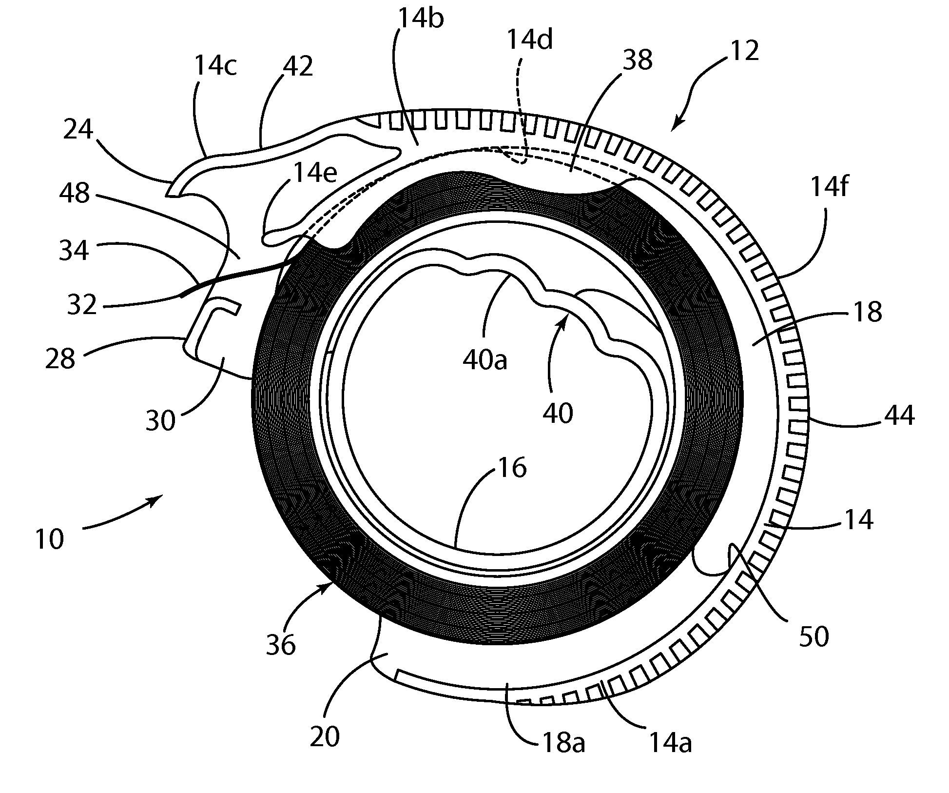
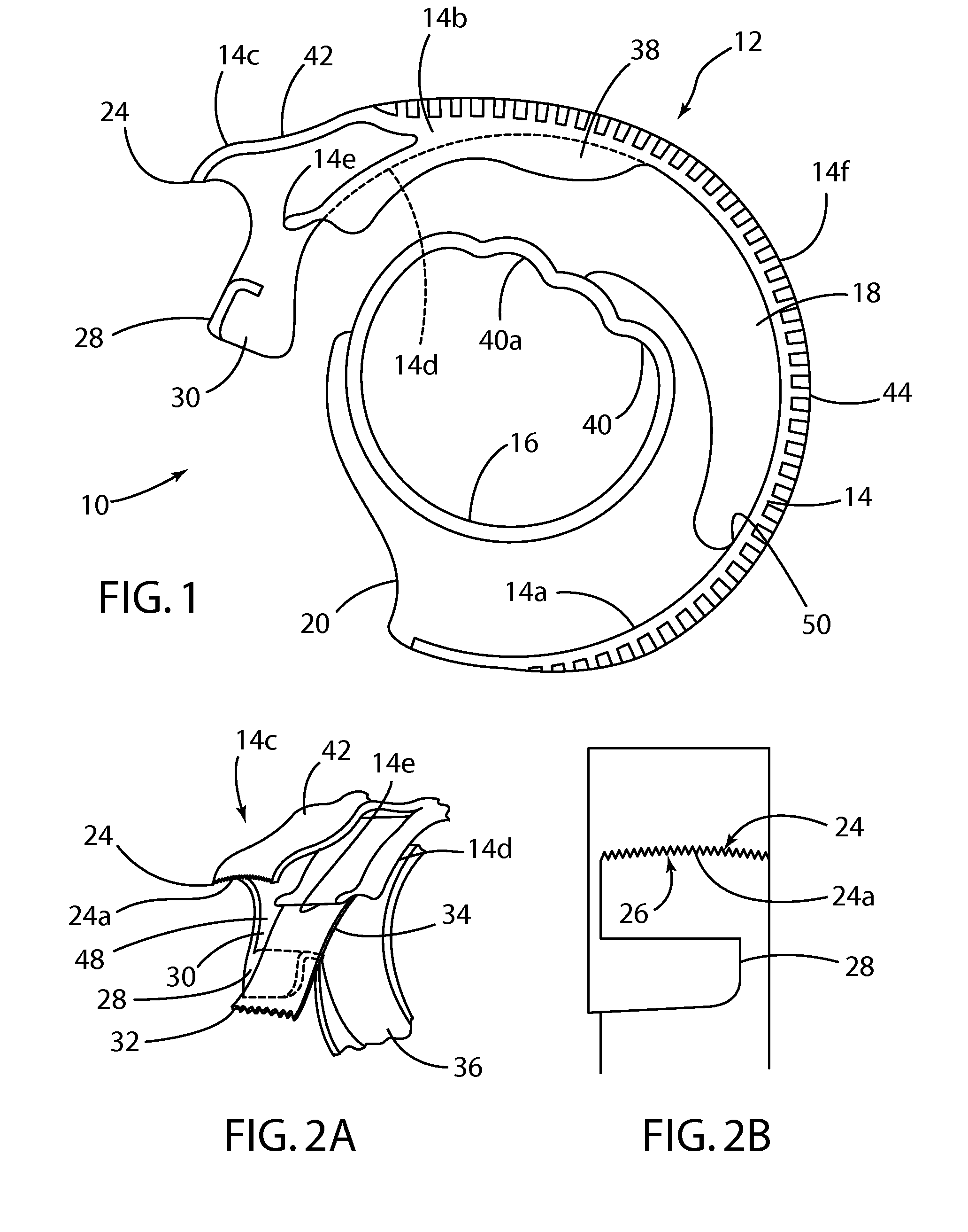
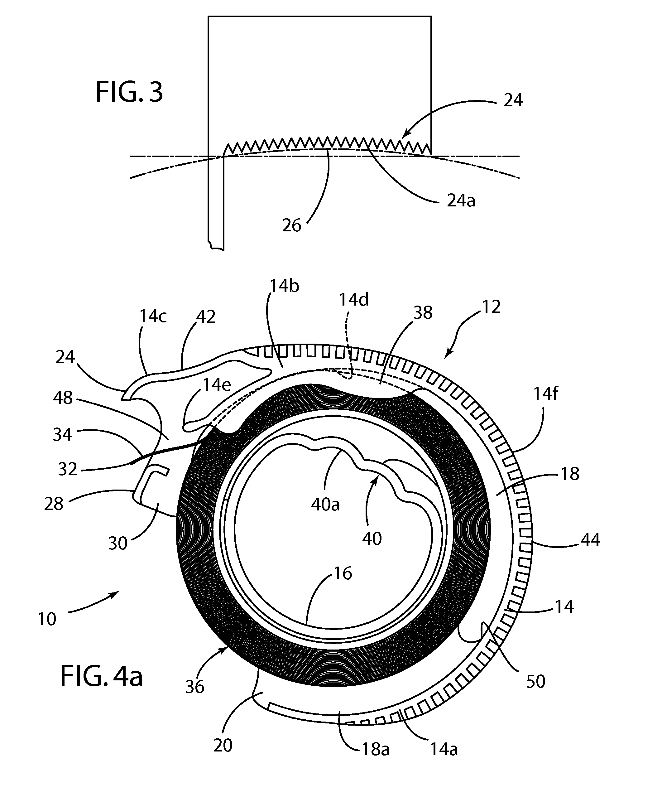
[0023]Referring to the Figures generally, and specifically to FIGS. 1, 4a and 4b, there is illustrated a tape dispenser, shown generally at 10. The dispenser 10 includes a substantially circular or semi-circular body 12 that is preferably formed as a unitary member; i.e., it consists of a single, integrally formed component. The body 12 may be formed of any number of conventional materials; however, plastic materials may be preferred. By way of a non-limiting example, the body 12 may ...


PUM

PropertyMeasurementUnit
lineal dimensionaaaaaaaaaa
widthaaaaaaaaaa
dimensionaaaaaaaaaa

Abstract

A tape dispenser including a body with having several functional elements formed thereon, including a cutting edge, an anvil, a guide, finger grips, and a thumb rest. The body also defines an opening for receiving a tape roll therein. The opening may be formed between an outer wall and an inner wall. The dispenser may also include a resilient element that causes the outer wall to contact the tape periphery, even as the tape roll is being depleted. The resilient element also allows for relatively easy loading and unloading of the tape roll without the need to remove or dissemble any parts of the system. A brake also allows the user to stop dispensing tape by pressing the outer wall against the outer periphery of the tape roll.

Description

CROSS-REFERENCE TO RELATED APPLICATION[0001]This application claims the benefit of U.S. Provisional Application No. 61 / 735,000, filed Dec. 8, 2012. The disclosure of the above application is incorporated herein by reference.BACKGROUND OF THE INVENTION[0002]1. Field of the Invention[0003]The present invention generally relates to dispensers, and more particularly, to a tape dispenser.[0004]2. Description of Related Art[0005]Conventional tape dispensers typically include sharp, linearly arranged cutting edges. Linearly arranged cutting edges can be difficult to use as they require that the tape be pulled at an angle to the cutting edge. A difficulty amplified when the cutting edge is not in an optimum position because the gap between the tape and the cutting edge increases, e.g., as the tape roll is depleted.[0006]Conventional tape dispensers may also include and / or use a plurality of parts to secure the tape roll therein, cut the tape, and make the end of the tape readily available f...

Claims


Application Information

Patent Timeline
Patent Type & Authority Applications(United States)
IPC IPC(8): B65H35/00
CPCB65H35/0026Y10T156/1365Y10T156/18
Inventor YARRISH, JOHN JOSEPHSHASKA, KASTRIOTKESLER, ERIC WILLIAM
Owner YARRISH JOHN JOSEPH
Why Eureka
Try Eureka