Systems and methods for magnetic material imaging

a magnetic material and imaging technology, applied in the field of medical imaging, can solve the problems of high equipment and/or operation cost, long acquisition time, and significant hardware or equipment modification

Active Publication Date: 2014-06-12
GENERAL ELECTRIC CO
View PDF4 Cites 20 Cited by
  • Summary
  • Abstract
  • Description
  • Claims
  • Application Information

AI Technical Summary

Benefits of technology

This patented describes two different systems for generating images on biological materials: Magnetography and Imaging Systems. These systems use separate components called Field Generators or Conductor Coils - Currents to create selected areas within the image space where variations can be detected by sensors placed near it's center. By combining these signals together they help identify small differences in magnectic properties such as iron content inside tissues. Additionally, this technology allows for precise movement of the imaging device itself during scanning without any external forces like gravity. Overall, both technical features improve accuracy and efficiency when analyzing biomedical data.

Problems solved by technology

The technical problem addressed in this patent is the need for a system and method to track surgical instruments without using harmful imaging modalities that require costly equipment or have long acquisition times. The current methods of X-ray fluoroscopy and MRI have limitations such as high dose of ionizing radiation and limited access to the patient. Ultrasound is another non-invasive imaging technology that has been applied to catheter tracking, but it requires modifications to the catheter and adds to the bulk and cost of the instrument. The patent proposes the use of magnetic particle imaging (MPI) as an alternative to these current methods. MPI is a non-invasive imaging modality that detects the magnetization change caused by magnetic particles and is free of ionizing radiation. However, current MPI systems are limited to imaging a single point and have long acquisition times.

Method used


Image

  • Systems and methods for magnetic material imaging
  • Systems and methods for magnetic material imaging
  • Systems and methods for magnetic material imaging

Examples


Embodiment Construction

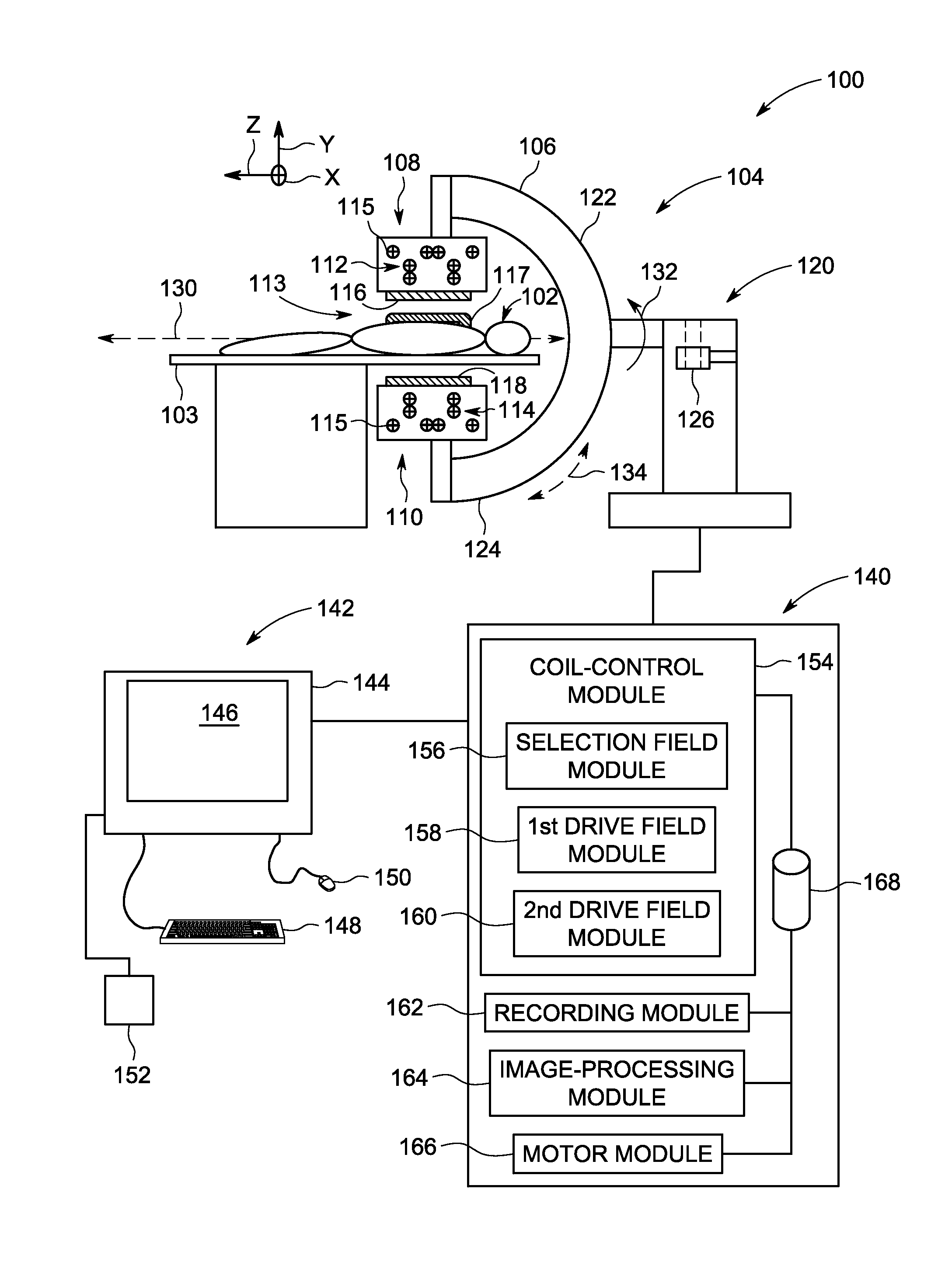
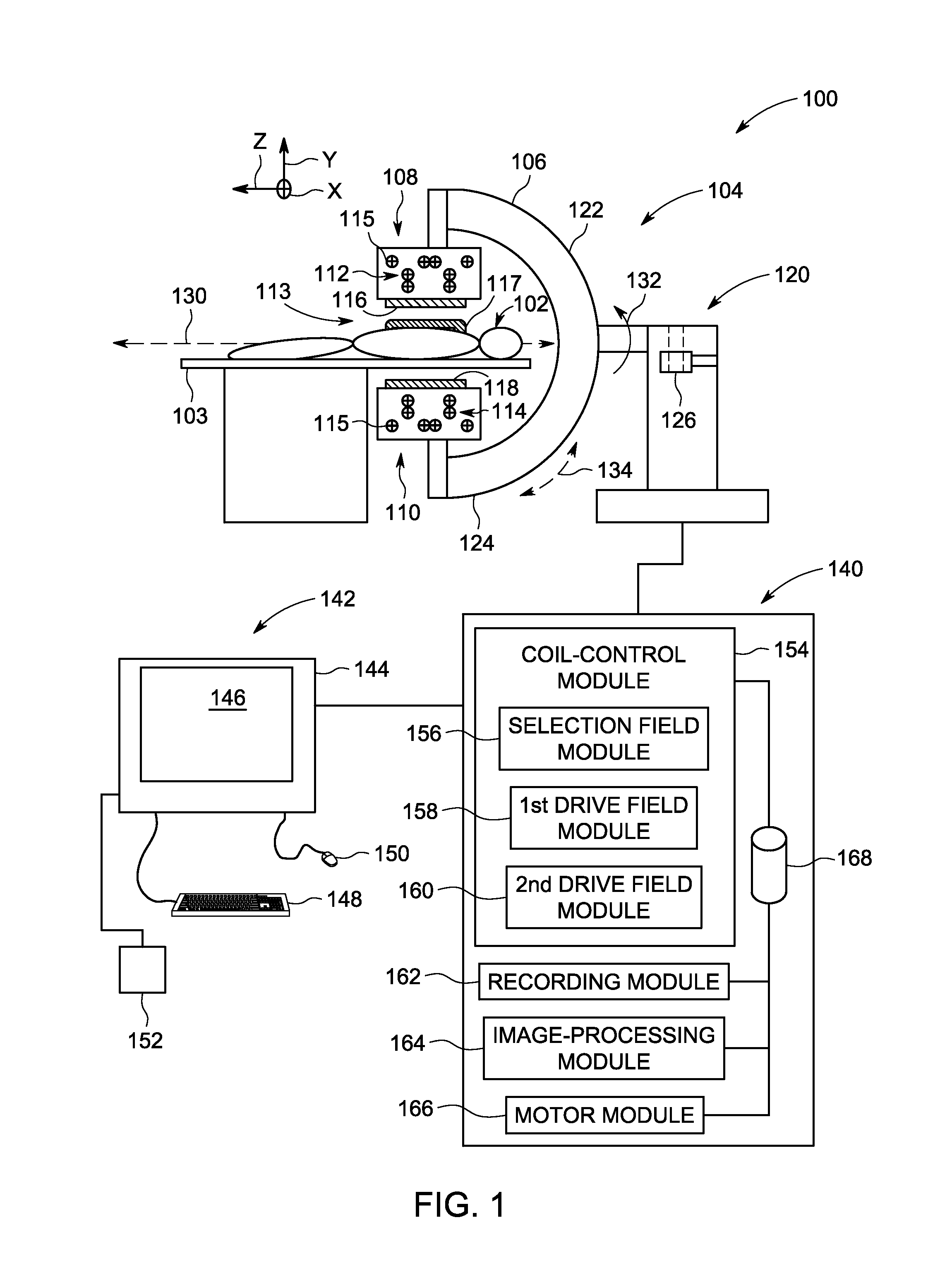
[0016]Embodiments described herein include systems and methods for imaging magnetic material in a spatial region. The systems and methods are based on a magnetic material imaging (MMI) modality, which may also be referred to as magnetic material tracking (MMT). MMI (or MMT) seeks to image a distribution of magnetic material (e.g., superparamagnetic iron oxide particles (SPIOs)) within the spatial region, such as within a patient's body. MMI detects changes in magnetization of the magnetic material that is proximate to a sensitive region (e.g., a field free point (FFP) or field free region (FFR)) that is generated by the MMI system. As used herein, the term “proximate to” includes the magnetic material being directly within or overlapping the sensitive region and also the magnetic material being suitably near the sensitive region. Magnetic material may be suitably near the sensitive region if an MMI system is capable of detecting changes in magnetization of the magnetic material for ...


PUM


Abstract

Magnetic material imaging (MMI) system including first and second sets of field-generating coils. Each of the field-generating coils of the first and second sets has an elongated segment that extends along an imaging axis of the medical imaging system. The imaging axis extends through a region-of-interest (ROI) of an object. The elongated segments of the first set of field-generating coils are positioned opposite the elongated segments of the second set of field-generating coils and the ROI is located between the first and second sets of field-generating coils. The MMI system also includes a coil-control module configured to control a flow of current through the first and second sets of field-generating coils to generate a selection field and to generate a drive field. The selection and drive fields combine to form a movable 1D field free region (FFR) that extends through the ROI.

Description


Claims


Application Information

Patent Timeline
Owner GENERAL ELECTRIC CO
Why Eureka
Try Eureka