Cardiac CT system and method for planning left atrial appendage isolation

a technology of ct and imaging system, applied in the field of cardiac implant systems, can solve the problems of high stroke risk of patients with a

Active Publication Date: 2010-06-29
GE MEDICAL SYST GLOBAL TECH CO LLC +1
View PDF84 Cites 192 Cited by
  • Summary
  • Abstract
  • Description
  • Claims
  • Application Information

AI Technical Summary

Benefits of technology

[0005]The above discussed and other drawbacks and deficiencies of the prior art are overcome or alleviated by a method for planning left atrial appendage (LM) occlusion for a patient. In an exemplary embodiment, the method includes obtaining non-invasive acquisition data from a medical imaging system, and generating a 3D model of the left atrium of the patient. One or more left atrial anatomical landmarks are identified on the 3D model, and saved views of the 3D model are registered on an interventional system. One or more of the registered saved views are visualized with the interventional system.
[0006]In another aspect, a method for planning left atrial appendage (LAA) occlusion for a patient includes obtaining acquisition data from a medical imaging system using a protocol directed toward the left atrium. The acquisition data is segmented using a 3D protocol so as to visualize the left atrium, including the LAA. A 3D model of the left atrium of the patient is generated, and one or more left atrial anatomical landmarks on the 3D model are identified. Saved views of the 3D model are registered on an interventional system, and one or more of the registered saved views are visualized on the interventional system. The orientation and size of the LM, as well as any anomalies associated therewith, are identified from the 3D model.
[0007]In still another aspect, a method for planning left atrial appendage (LAA) occlusion for a patient includes obtaining acquisition data from a cardiac imaging system such as computed tomography (CT) scanner using a protocol directed toward the left atrium. The acquisition data are segmented using a 3D protocol so as to visualize the left atrium, including the LAA. A 3D model of the left atrium of the patient is generated, and one or more left atrial anatomical landmarks on the 3D model are identified. Saved views of the 3D model are registered on a fluoroscopy system, and one or more of the registered saved views are visualized with the fluoroscopy system. The orientation and size of the LAA, as well as any anomalies associated therewith, are identified from the 3D model.
[0008]In still another aspect, a system for planning left atrial appendage (LAA) occlusion for a patient includes a medical imaging system for generating non-invasive acquisition data, and an image generation subsystem for receiving the acquisition data and generating one or more images of the left atrium of the patient. An operator console or post-processing device is configured for identifying one or more left atrial anatomical landmarks on the one or more images. The workstation includes post processing software for saving views of the 3D model that can be registered on an interventional system. The interventional system is configured for visualizing one or more of the registered saved views therewith and identifying the orientation and size of the LAA.
[0009]In still another aspect, a system for planning left atrial appendage occlusion for a patient includes a cardiac computed tomography (CT) imaging system for generating acquisition data, the CT imaging system using a protocol directed toward the left atrium. An image generation subsystem receives the acquisition data and generates one or more images of the left atrium of the patient. The image generation system is further configured for segmenting the acquisition data using a 3D protocol so as to visualize the left atrium, including the LAA. An operator console is configured for identifying one or more left atrial anatomical landmarks on the one or more images, and a workstation includes post processing software for registering saved views of the 3D model on a fluoroscopy system. The fluoroscopy system is configured for visualizing one or more of the registered saved views therewith and identifying the orientation and size of the LAA.

Problems solved by technology

Patients with AF have a high risk of stroke, and about 15 percent of all strokes occur in people with atrial fibrillation.
Such clots can block a blood vessel leading to the brain, thereby causing a stroke.
In clinical practice, however, in over 40 percent of patients the drug is contraindicated or cannot be used because of the side effects, such as bleeding.

Method used


Image

  • Cardiac CT system and method for planning left atrial appendage isolation
  • Cardiac CT system and method for planning left atrial appendage isolation
  • Cardiac CT system and method for planning left atrial appendage isolation

Examples


Embodiment Construction

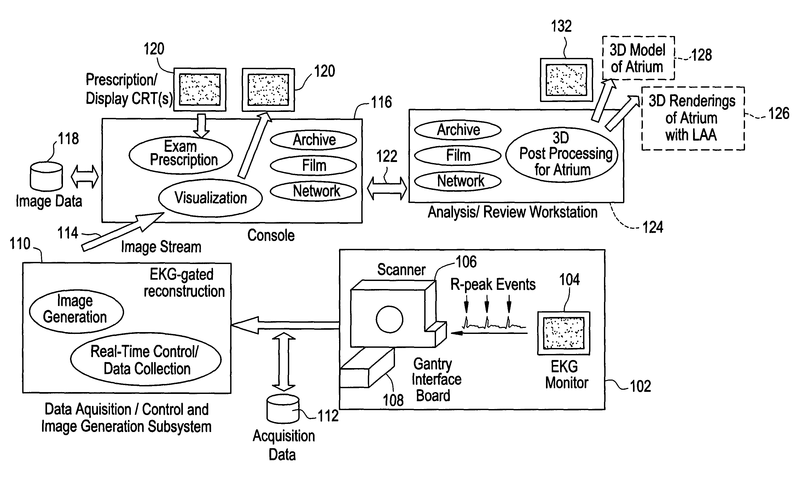
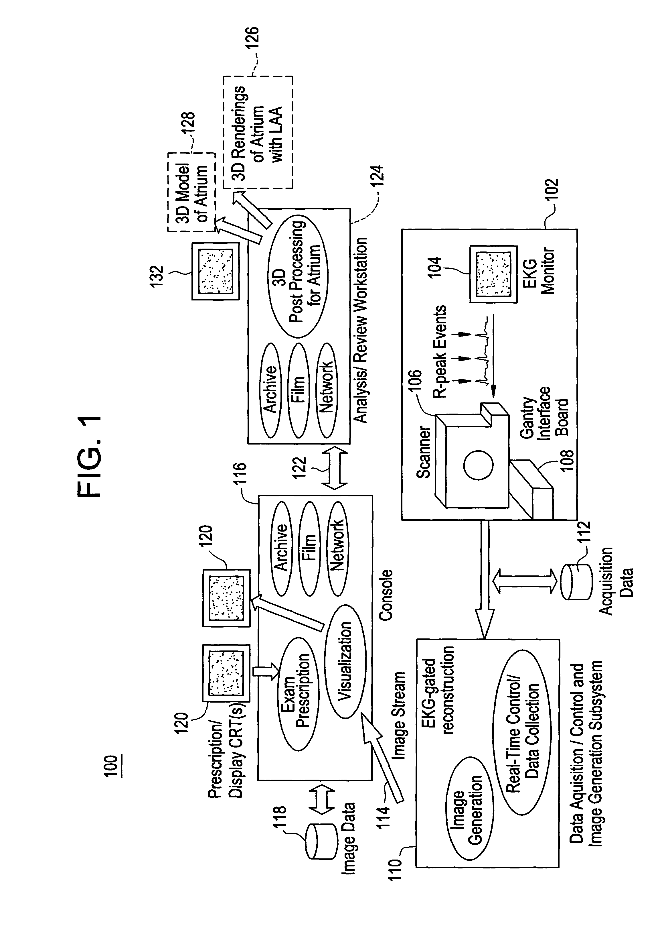
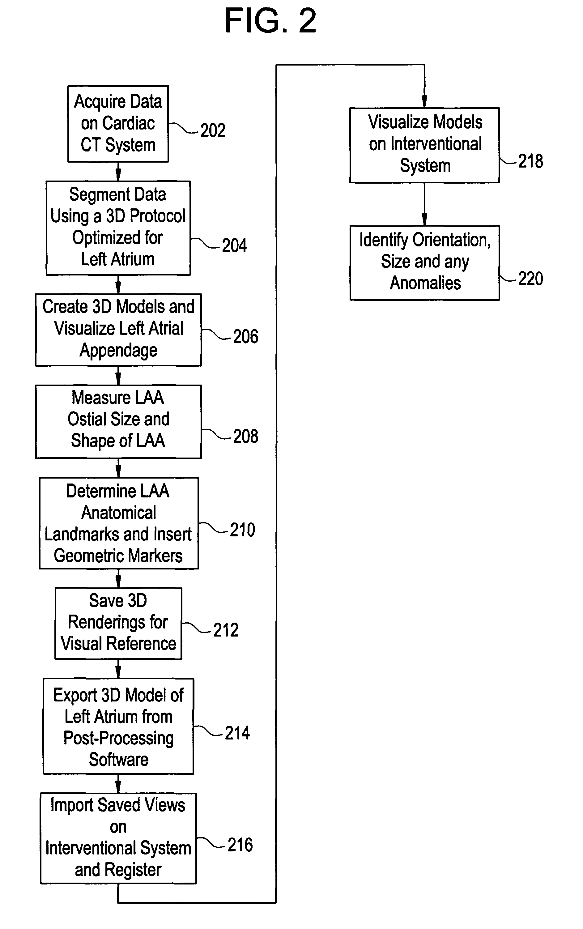
[0013]Disclosed herein is a cardiac computed tomography (CT) system and method for LAA isolation / occlusion that provides information for planning interventional procedures that enable an electrophysiologist, cardiologist and / or surgeon to plan in advance a desired approach to take for the procedure. Additionally, with a more detailed three-dimensional (3D) geometrical representation of the LM, as may be obtained from imaging modalities such as CT, magnetic resonance (MR) and ultrasound, the practitioner can identify the orientation, size and any anomalies of the LM. Thus, a device or implant of the correct size may be selected during planning so as to avoid the problem of incorrectly sized implants encountered with this procedure. The 3D images obtained may also be used to plan for isolation of LAA from outside (i.e., epicardially).

[0014]Although the exemplary embodiments illustrated hereinafter are described in the context of a CT imaging system, it will be appreciated that other i...


PUM


Abstract

A method for planning left atrial appendage (LAA) occlusion for a patient includes obtaining acquisition data from a medical imaging system, and generating a 3D model of the left atrium of the patient. One or more left atrial anatomical landmarks are identified on the 3D model, and saved views of the 3D model are registered on an interventional system. One or more of the registered saved views are visualized with the interventional system.

Description

BACKGROUND OF THE INVENTION[0001]The present disclosure relates generally to cardiac implant systems and, more particularly, to a cardiac imaging system and method for planning isolation of the left atrial appendage of the heart.[0002]Atrial fibrillation (AF) is an arrhythmia in which the atria (upper chambers of the heart) stop contracting properly as they fibrillate, and is the most common of heart rhythm irregularities. It is estimated that over 2.2 million Americans have been diagnosed with AF, with over 140,000 new cases being diagnosed each year. Patients with AF have a high risk of stroke, and about 15 percent of all strokes occur in people with atrial fibrillation. Each year, about 600,000 Americans suffer a new or recurrent stroke. In 1991, the Framingham study showed that a diagnosis of AF increased the risk of stroke 3 to 5 times higher, rising from 1.5% in the fifth decade of life to over 23% by the eighth decade.[0003]More specifically, previous studies indicate that mo...

Claims


Application Information

Patent Timeline
Patent Type & Authority Patents(United States)
IPC IPC(8): G06K9/00A61B6/00A61B6/03G06T7/00G06T17/40G16H20/30G16H30/40
CPCA61B6/032A61B6/503G06T19/00G06F19/321G06F19/3437G06T7/0028A61B5/7289A61B6/541A61B8/0883G06T2210/41G06T2207/30048G06F19/3481G06T7/33G16H50/50G16H20/30G16H30/40
Inventor OKERLUND, DARIN R.SRA, JASBIR S.VASS, MELISSA L.REDDY, SHANKARA B.
Owner GE MEDICAL SYST GLOBAL TECH CO LLC
Why Eureka
Try Eureka