Fault detection system and associated method

Active Publication Date: 2014-06-19
GENERAL ELECTRIC CO
View PDF5 Cites 117 Cited by
  • Summary
  • Abstract
  • Description
  • Claims
  • Application Information

AI Technical Summary

Problems solved by technology

Electromechanical machines having electrical generators, motors and a drive train may generate torsional and radial vibrations due to presence of defective components such as bearings, gears, or the like.
Mechanical faults in electromechanical systems having a drive train may generate vibrations at the rotor rotating frequency.
But, it has been found that vibration signals cannot detect all types of fault

Method used


Image

  • Fault detection system and associated method
  • Fault detection system and associated method
  • Fault detection system and associated method

Examples


Embodiment Construction

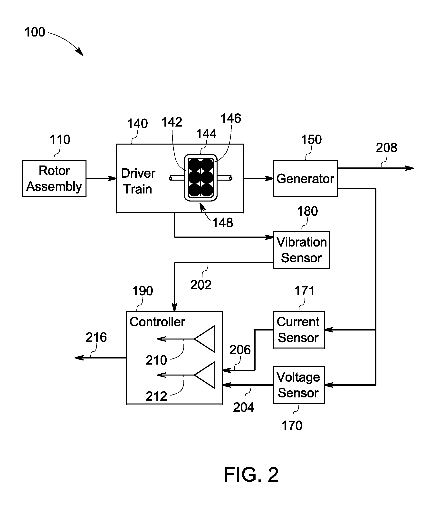
[0014]Embodiments of the present technology relate to a system and method for detecting faults in a mechanical device of an EMM. A measured electrical signal is received from an electrical device of an EMM. Further, a measured vibration signal is received from the mechanical device of the EMM, coupled to the electrical device. A first signal signature is determined based on the measured electrical signal and a second signal signature is determined based on the measured vibration signal. One or more diagnostic parameters are determined based on the first signal signature and the second signal signature. One or more faults of the mechanical device are determined based on the determined one or more diagnostic parameters.

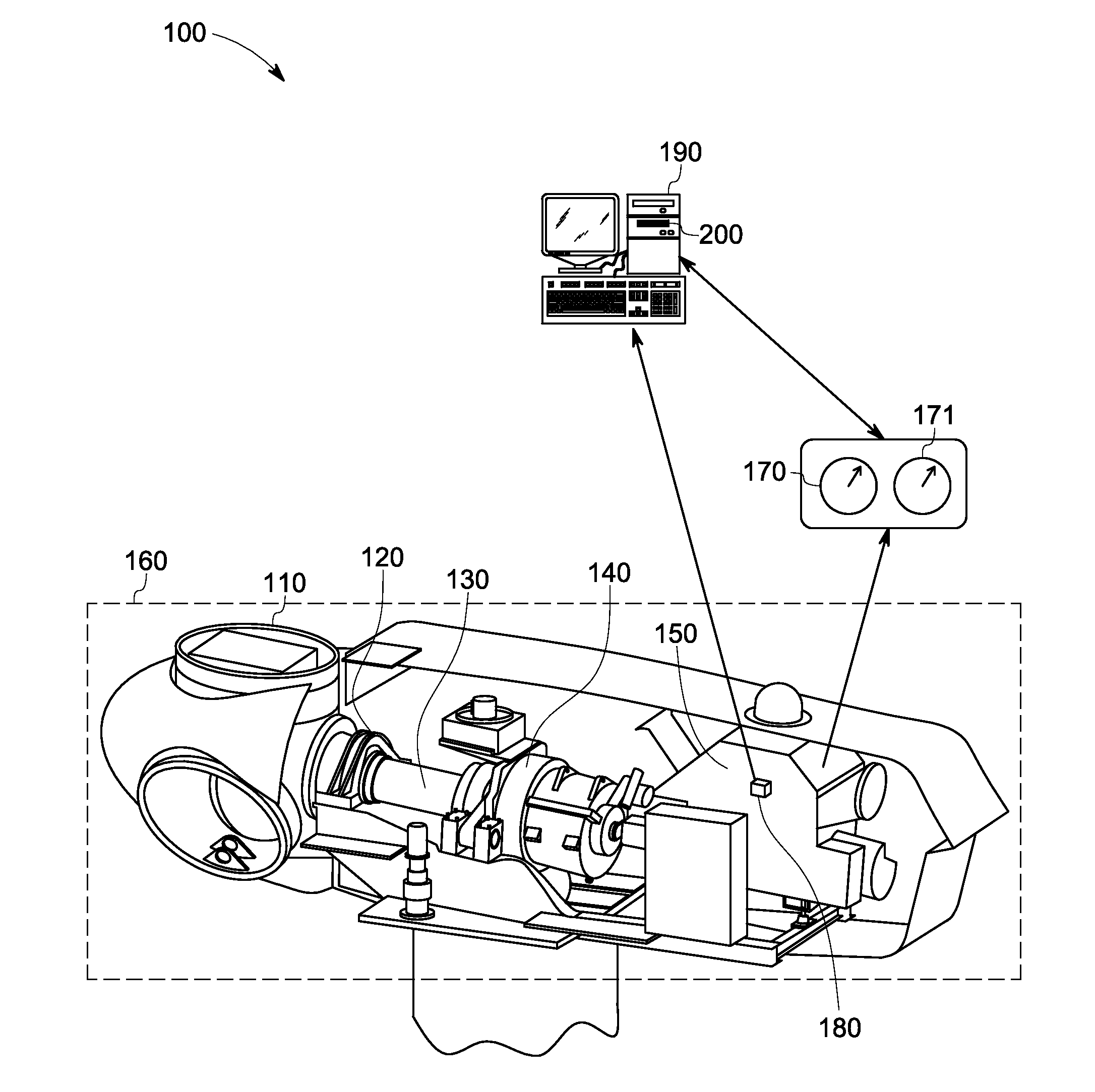
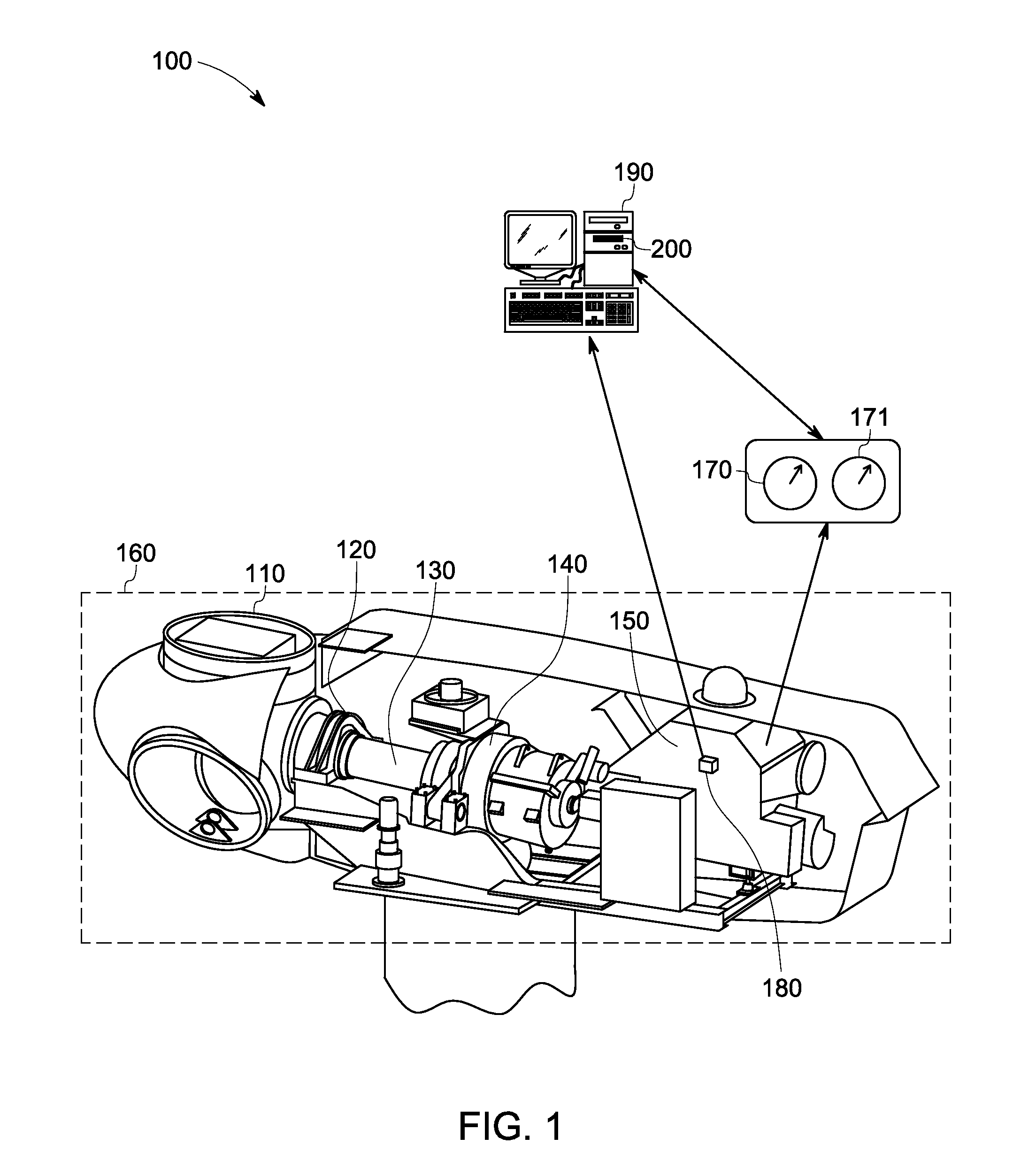
[0015]FIG. 1 is a diagrammatic illustration of a system 100 in accordance with an exemplary embodiment of the present invention. The system 100 includes an EMM 160 having at least one electrical device 150 and a mechanical device 140. The system 100 further includes two...


PUM


Abstract

A method implemented using a controller based device includes receiving a measured electrical signal from an electrical device of an electromechanical device and receiving a measured vibration signal from a mechanical device of the electromechanical device, coupled to the electrical device. The method further includes determining a first signal signature based on the measured electrical signal and determining a second signal signature based on the measured vibration signal. The method also includes determining a diagnostic parameter based on the first signal signature and the second signal signature and determining a fault in the mechanical device based on the diagnostic parameter.

Description

BACKGROUND[0001]The technology disclosed herein, generally relates to fault detection of electromechanical machines (EMM). More specifically, the subject matter relate to detection of faults in various components of a drivetrain in an electromechanical machine.[0002]Electromechanical machines having electrical generators, motors and a drive train may generate torsional and radial vibrations due to presence of defective components such as bearings, gears, or the like. Conventionally, vibration analysis of electro mechanical machines may be performed to monitor operating conditions of the machine. Mechanical faults in electromechanical systems having a drive train may generate vibrations at the rotor rotating frequency. Analysis of rotor rotating frequency facilitates to detect mechanical faults associated with the drive train. Vibration signals may be used to effectively monitor radial vibrations. But, it has been found that vibration signals cannot detect all types of faults associa...

Claims


Application Information

Patent Timeline
IPC IPC(8): G01R31/34
CPCG01R31/34G01R31/343G01M13/045
Inventor NETI, PRABHAKARZHANG, PINJIA
Owner GENERAL ELECTRIC CO
Why Eureka
Try Eureka