Head-mounted display device, control method for head-mounted display device, and work supporting system

a display device and control method technology, applied in the direction of portable computers, instruments, computing, etc., can solve the problems of difficulty in coping with unexpected dangers, difficulty in estimating warning points, and lack of versatility in the method of estimating warning points

Active Publication Date: 2014-06-19
SEIKO EPSON CORP
View PDF22 Cites 200 Cited by
  • Summary
  • Abstract
  • Description
  • Claims
  • Application Information

AI Technical Summary

Benefits of technology

[0010](1) An aspect of the invention provides a head-mounted display device for enabling a user to simultaneously visually recognize a virtual image and an outside scene. The head-mounted display device includes: an image acquiring unit configured to acquire an image in a visual field direction of the user in a wearing state of the head-mounted display device; a warning-information generating unit configured to generate warning information, which is an image for calling the user's attention, on the basis of the image acquired by the image acquiring unit; and an image display unit configured to cause the user to visually recognize the wa...

Problems solved by technology

In the techniques, since the image recognition is performed based on the dangerous area specifying information individually prepared in advance, it is difficult to cope with an unexpected danger.
Similarly, in the techniques, since a component having an abnormal temperature is detected on the basis of the proper temperature database individually prepared in advance, it is difficult to cope with an unexpected danger.
That is, the techniques have a problem in that, since information individually and specifically prepared in advance is necessary for estimating a warning point such as a danger, a method of estimating a warning point lacks versatility.
The techniques have a problem in that it is difficult to inform the user of a warning point such as a danger.
The techniques have a problem in that, since a visible image is superimposed on the entire area of the visual field of the...

Method used


Image

  • Head-mounted display device, control method for head-mounted display device, and work supporting system
  • Head-mounted display device, control method for head-mounted display device, and work supporting system
  • Head-mounted display device, control method for head-mounted display device, and work supporting system

Examples


first embodiment

A. First Embodiment

A-1. Configuration of a Head-Mounted Display Device

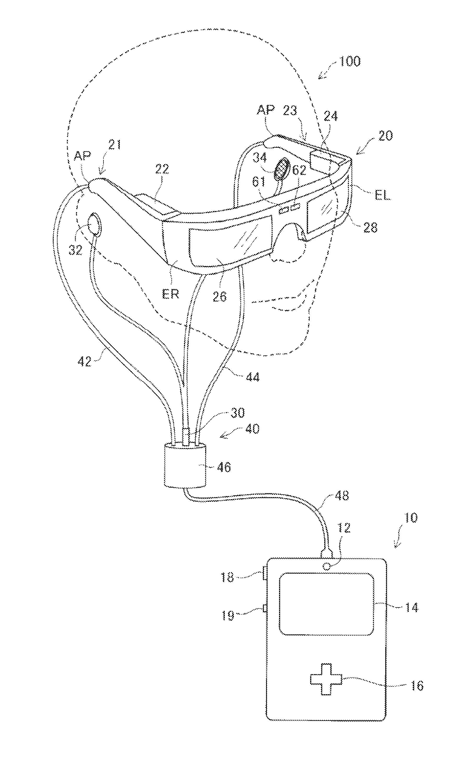
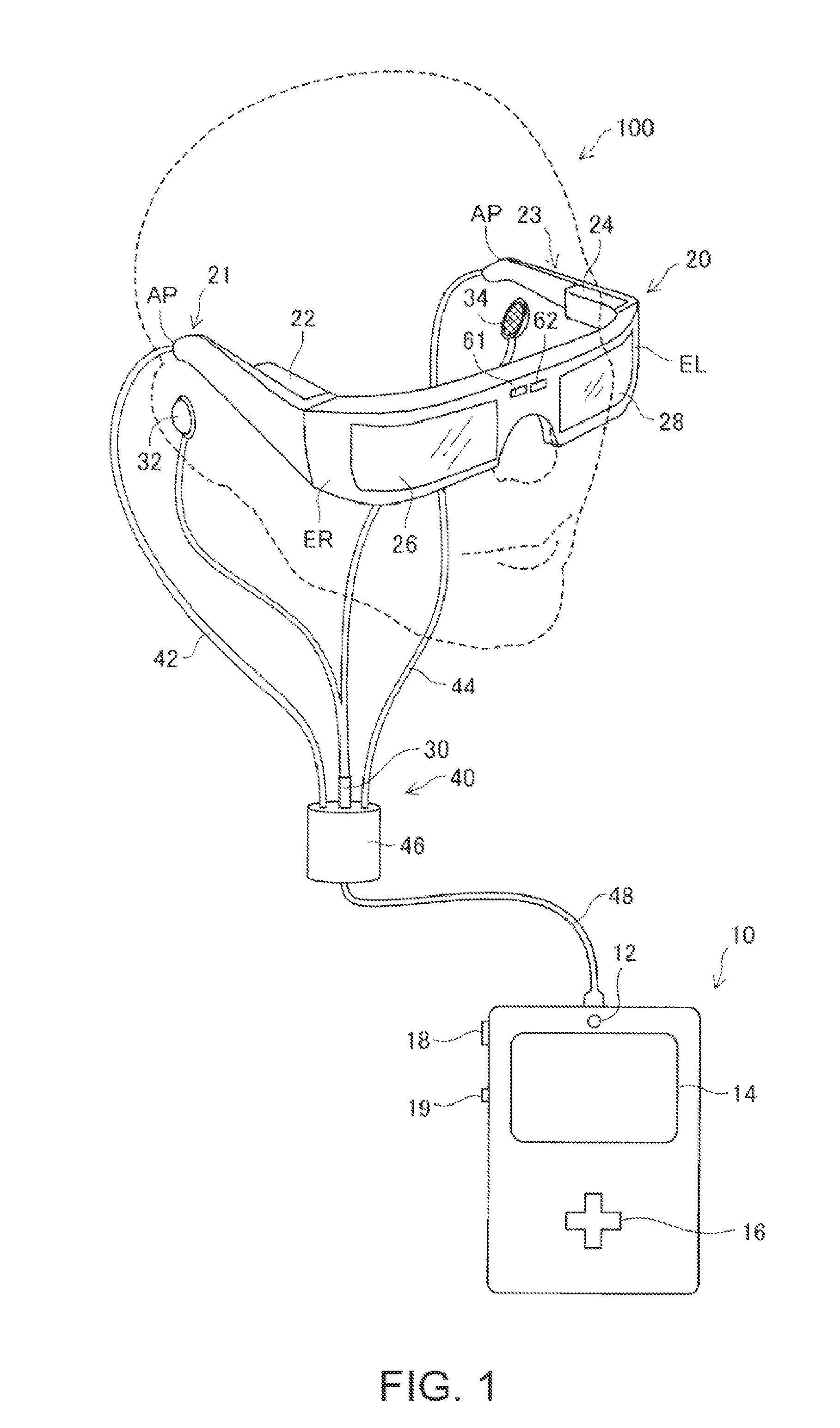
[0060]FIG. 1 is an explanatory diagram showing the schematic configuration of a head-mounted display device in a first embodiment of the invention. A head-mounted display device 100 is a display device mounted on the head and is also called head mounted display (HMD). The head mounted display 100 in this embodiment is an optically transmissive head-mounted display device for enabling a user to directly visually recognize an outside scene simultaneously with visually recognizing a virtual image.

[0061]The head mounted display 100 includes an image display unit 20 configured to cause the user to visually recognize a virtual image in a state in which the head mounted display 100 is mounted on the head of the user and a control unit (a controller) 10 configured to control the image display unit 20.

[0062]The image display unit 20 is a mounted body mounted on the head of the user. In this embodiment, the image display un...

second embodiment

B. Second Embodiment

[0130]In a second embodiment of the invention, a configuration capable of supporting work performed by a user and informing the user of a warning point such as a danger incidental to the work in a head-mounted display device is explained. In the following explanation, only portions having configurations and operations different from the configurations and the operations in the first embodiment are explained. In the figures, components same as the components in the first embodiment are denoted by reference numerals and signs same as the reference numerals and signs in the first embodiment explained above. Detailed explanation of the components is omitted.

B-1. Configuration of the Head-Mounted Display Device

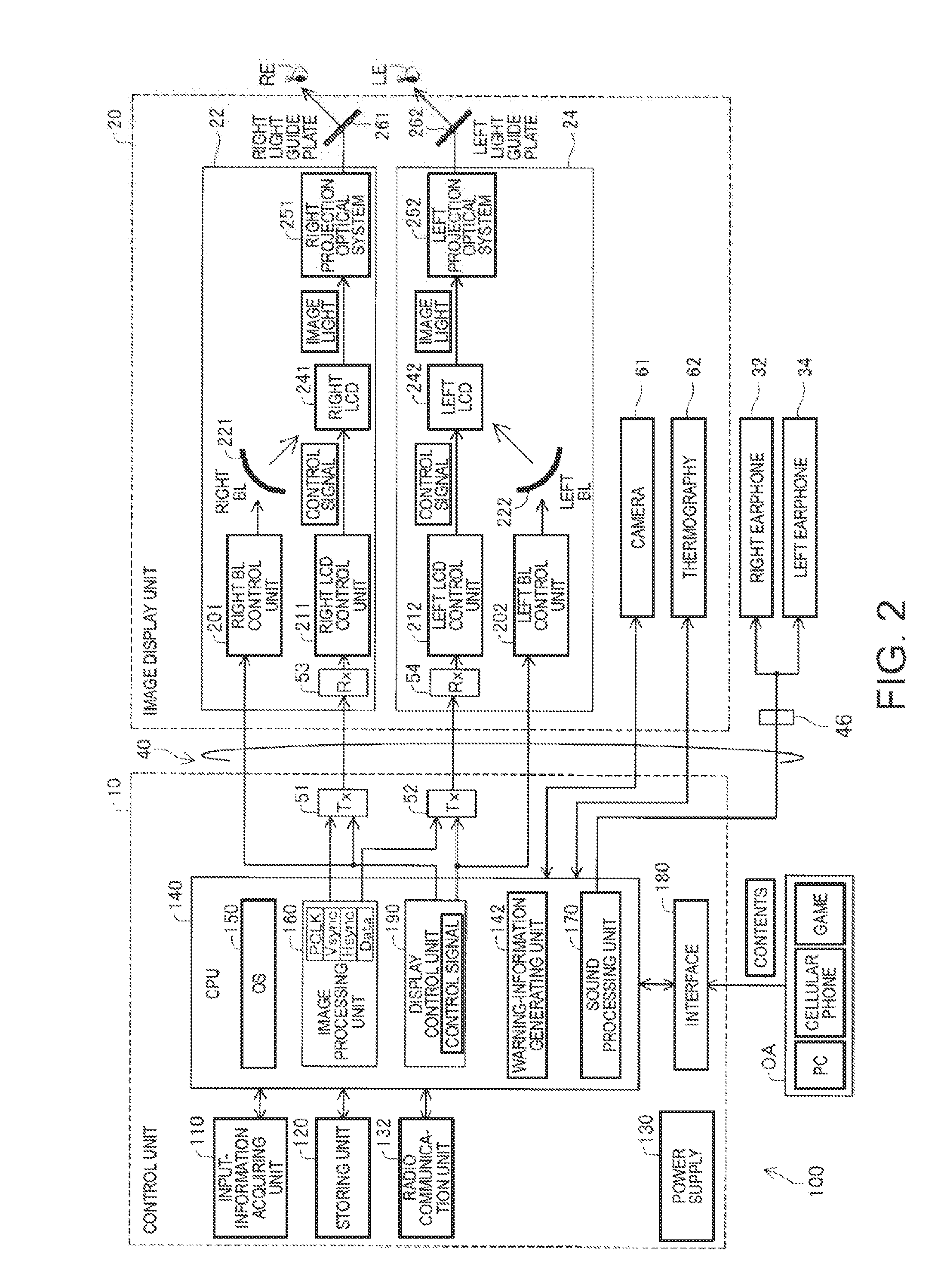
[0131]FIG. 11 is a block diagram functionally showing the configuration of a head mounted display 100a in the second embodiment. A difference from the first embodiment shown in FIG. 2 is that the head mounted display 100a includes a control unit 10a instead of t...

modification 1

[0185]In the embodiments, the configuration of the head mounted display is illustrated. However, the configuration of the head mounted display can be arbitrarily set without departing from the spirit of the invention. For example, addition, deletion, conversion, and the like of the components can be performed.

[0186]The allocation of the components to the control unit and the image display unit in the embodiments is only an example. Various forms can be adopted. For example, forms explained below may be adopted: (i) a form in which the processing functions such as the CPU and the memory are mounted on the control unit and only the display function is mounted on the image display unit, (ii) a form in which the processing functions such as the CPU and the memory are mounted on both of the control unit and the image display unit, (iii) a form in which the control unit and the image display unit are integrated (e.g., a form in which the control unit is included in the image display unit ...


PUM


Abstract

A head-mounted display device for enabling a user to simultaneously visually recognize a virtual image and an outside scene includes a warning-information generating unit configured to generate warning information, which is an image for calling the user's attention and an image display unit configured to cause the user to visually recognize the warning information as the virtual image.

Description

CROSS-REFERENCE[0001]This application is based upon and claims priorities from Japanese Patent Application No. 2012-272166 filed on Dec. 13, 2012 and Japanese Patent Application No. 2012-272167 filed on Dec. 13, 2012, the entire contents of all of which are incorporated herein by reference.BACKGROUND[0002]1. Technical Field[0003]The present invention relates to a head-mounted display device.[0004]2. Related Art[0005]There is known a technique called augmented reality (AR) for additionally presenting information in an actual environment using a computer. The augmented reality is mounted on, for example, head mounted display (hereinafter referred to as “head-mounted display device”). The head-mounted display device picks up an image of an outside scene with a camera, recognizes the picked-up image, and generates information for additional presentation. In a non-transmissive head-mounted display device that blocks the visual field of a user when the user wears the head-mounted display ...

Claims


Application Information

Patent Timeline
IPC IPC(8): G02B27/01
CPCG02B27/0172G02B27/017G02B2027/0141G02B2027/0178G02B2027/0138G02B2027/014G06F1/163G06F3/011
Inventor KIMURA, FUSASHI
Owner SEIKO EPSON CORP
Why Eureka
Try Eureka