Pallet

Active Publication Date: 2014-06-26
TCL CHINA STAR OPTOELECTRONICS TECH CO LTD
0 Cites 3 Cited by

AI-Extracted Technical Summary

Problems solved by technology

However, the conventional pallet is often made integrally as a unity and causes a waste of space in transportation and stacking.
Spaces are formed between legs 102, so that a number...

Benefits of technology

[0005]An object of the present invention is to provide a pallet, which has an adjustable size to be fit for packagi...

Abstract

The present invention provides a pallet, which includes a pallet body, a plurality of recesses formed in a bottom of the pallet body, two retention tabs mounted to the bottom of the pallet body and respectively extending downward from two opposite sides of each of the recesses, and a plurality of legs mounted to the retention tabs and respectively receivable in the recesses. The pallet includes the rotatable legs, so that in using the pallet, the legs are rotated out and the coupling pins are applied to fix the legs for supporting and when the pallet is not in use, the coupling pins are removed to allow the legs to rotate in order to set the legs in recesses, whereby the pallet occupies a reduced amount of space for storage and transportation and thus the capacity of storage and transportation can be improved to thus lower down transportation cost.

Application Domain

Rigid containersDamagable goods packaging

Technology Topic

PalletTransportation cost

Image

  • Pallet
  • Pallet
  • Pallet

Examples

  • Experimental program(1)

Example

[0037]To further expound the technical solution adopted in the present invention and the advantages thereof, a detailed description is given to a preferred embodiment of the present invention and the attached drawings.
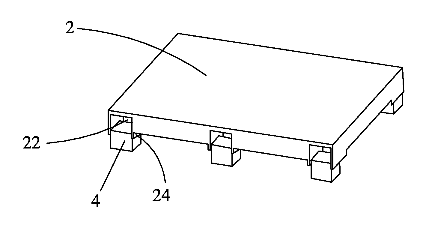
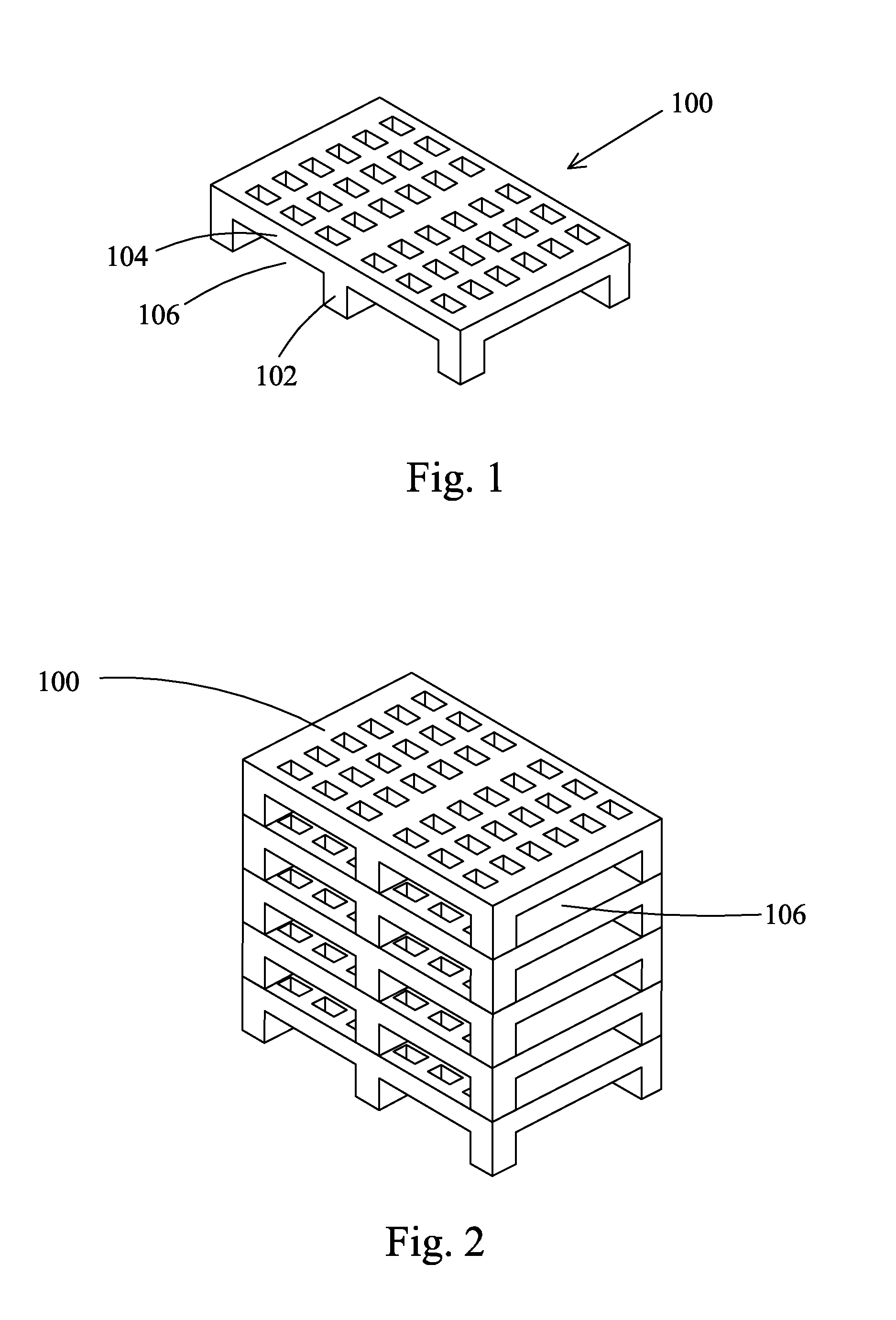
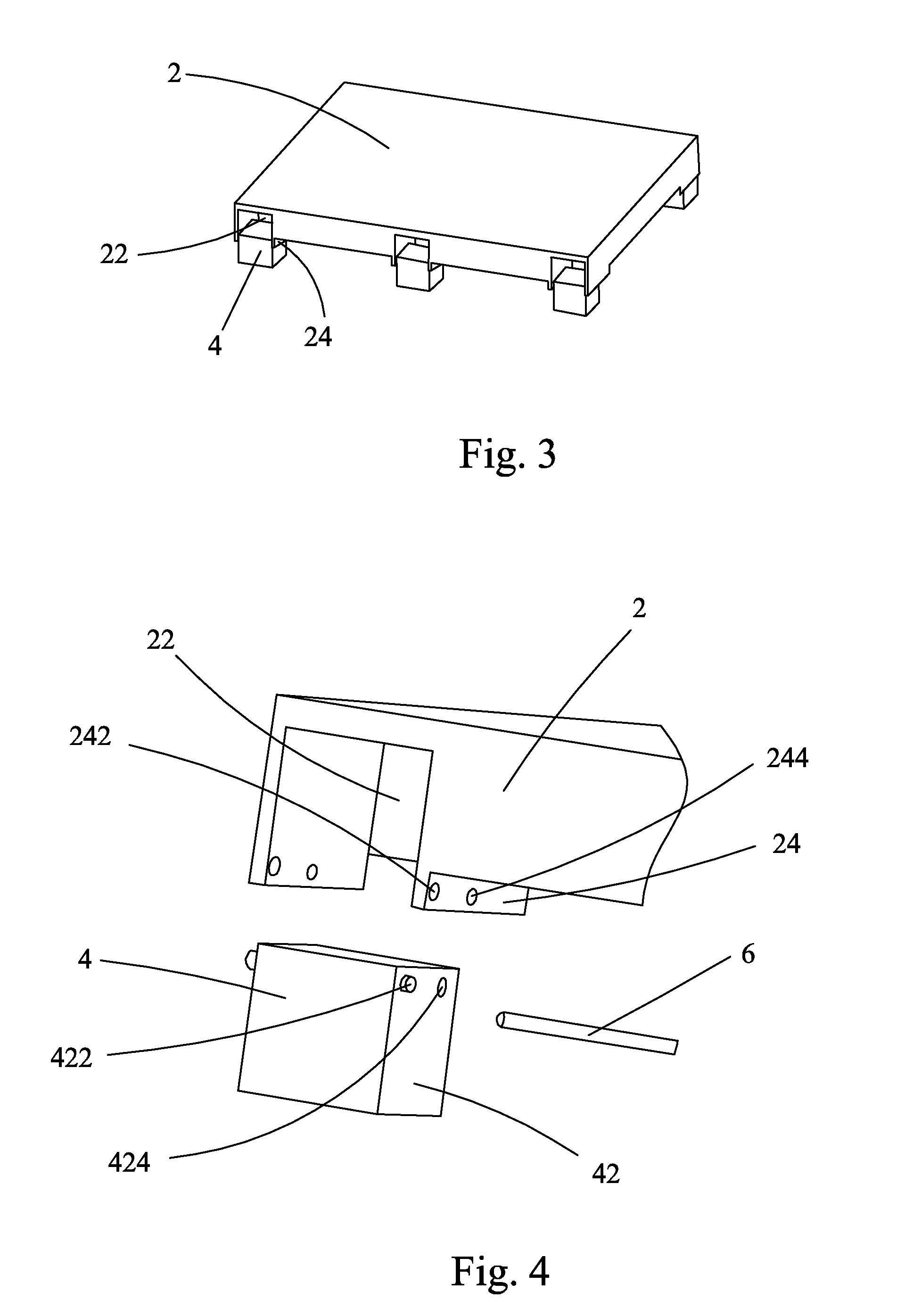
[0038]Referring to FIGS. 3-8, the present invention provides a pallet, which comprises a pallet body 2, a plurality of recesses 22 formed in a bottom of the pallet body 2, two retention tabs 24 mounted to the bottom of the pallet body 2 and respectively extending downward from two opposite sides of each of the recesses 22, and a plurality of legs 4 mounted to the retention tabs 24 and respectively receivable in the recesses 22. To use, the legs 4 are rotated out of the recesses 22 to support the pallet body 2. When not in use, the legs 4 are rotated 270° to get into the recesses 22 in order to reduce space occupation rate.
[0039]In the instant embodiment, the pallet body 2 is in the form of a flat board. The legs 4 are of a cubic form and each has two opposite side faces 42 each of which forms a projection 422. The retention tabs 24 form first through holes 242 corresponding to the projections 422. The projections 422 are received and retained in the first through holes 242 in such a way that the legs 4 are rotatably coupled to the retention tabs 24. To use, the legs 4 are rotated out of the recesses 22 to support the pallet body 2 and to store, the legs 4 are rotated 270° to get into the recesses 22 in order to reduce space occupation rate.
[0040]The legs 4 each form a second through hole 424 extending through the two opposite side faces 42. The retention tabs 24 each form a third through hole 244 corresponding to the second through hole 424. A coupling pin 6 is receivable through the third through holes 244 and the second through hole 424 to retain the leg 4 to the retention tabs 24. To use the pallet, the legs 4 are rotated out of the recesses 22 and the coupling pins 6 are respectively put through the third through holes 244 and the corresponding second through hole 424 to fix the legs 4 in order to improve the strength of coupling therebetween.
[0041]The recesses 22 have a depth that is greater than or equal to a diagonal length of the side faces 42 of the legs 4. Preferably, the depth of the recesses 22 is greater than the diagonal length of the side faces 42 of the legs 4 to allow easy rotation of the legs 4 into the recesses 22.
[0042]In the instant embodiment, the pallet body 2 comprises six recesses 22 formed in the bottom thereof. The six recesses 22 are arranged along two opposite sides of the pallet body 2. The legs 4 are of a number of six and are respectively mounted in the six recesses 22. Three of the legs 4 that are located along the same side can be fixed by a common coupling pin 6 in order to improve operation efficiency and reduce manufacturing cost.
[0043]The pallet body 2 and the retention tabs 24 are integrally formed together with a material, such as plastics or wood. The legs 4 and the projections 422 thereof are integrally formed together with a material, such as plastics or wood. The coupling pins 6 are made of a material such as plastics and wood, which shows a predetermined strength and stiffness in order to improve the quality of pallet.
[0044]In summary, the present invention provides a pallet, which comprises rotatable legs, so that in using the pallet, the legs are rotated out and coupling pins are applied to fix the legs for supporting and when the pallet is not in use, the coupling pins are removed to allow the legs to rotate in order to set the legs in recesses, whereby the pallet in entirety occupies a reduced amount of space for storage and transportation and thus the capacity of storage and transportation can be improved to thus lower down transportation cost.
[0045]Based on the description given above, those having ordinary skills of the art may easily contemplate various changes and modifications of the technical solution and technical ideas of the present invention and all these changes and modifications are considered within the protection scope of right for the present invention.

PUM

no PUM

Description & Claims & Application Information

We can also present the details of the Description, Claims and Application information to help users get a comprehensive understanding of the technical details of the patent, such as background art, summary of invention, brief description of drawings, description of embodiments, and other original content. On the other hand, users can also determine the specific scope of protection of the technology through the list of claims; as well as understand the changes in the life cycle of the technology with the presentation of the patent timeline. Login to view more.
Why Eureka
Try Eureka