
Apparatus for use in a fall detector or fall detection system, and a method of operating the same

a technology for fall detection and apparatus, applied in the field of apparatus for use in fall detectors or fall detection systems, can solve the problems of significant injuries, inability to push the button, and help does not arrive for a significant period of time, and achieve the effect of minimizing the power consumption of the fall detector or sensor unit in the fall detection system

Active Publication Date: 2014-07-10
KONINKLJIJKE PHILIPS NV
View PDF2 Cites 48 Cited by
  • Summary
  • Abstract
  • Description
  • Claims
  • Application Information

AI Technical Summary

Benefits of technology

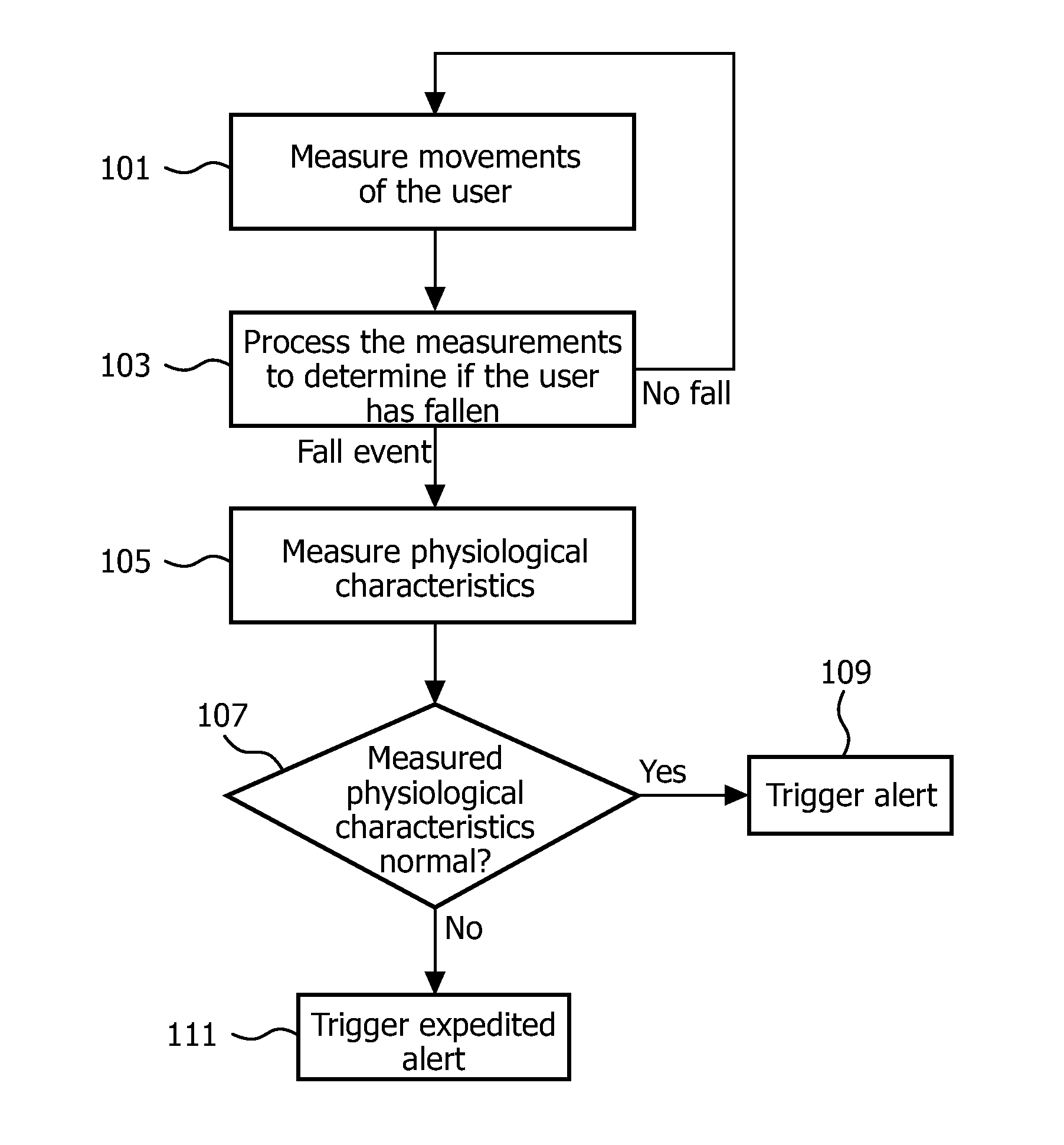
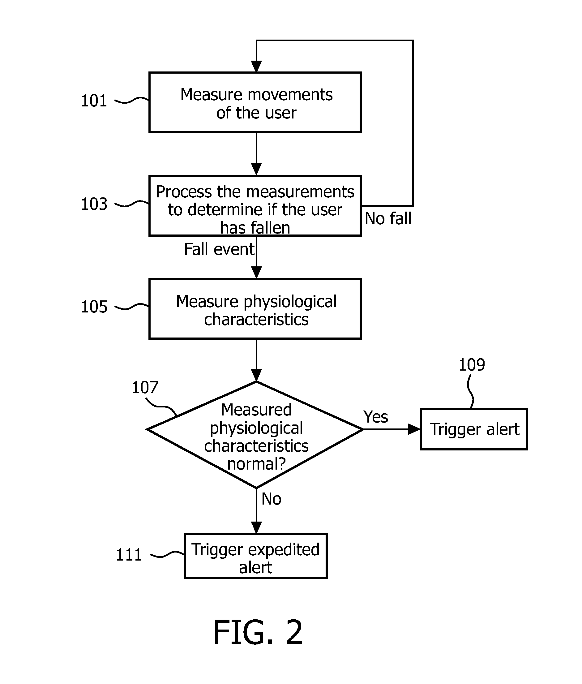
[0035]Thus, the invention provides a fall detector or fall detection system that uses a measurement of one or more physiological characteristics following a detected fall event to determine whether to expedite an alert that the user has fallen and requires assistance. Furthermore, in preferred embodiments, as the physiological characteristic monitoring is only triggered when a fall has been detected, the power consumption of the fall detector or sensor unit in a fall detection system can be minimized.

Problems solved by technology

Falls affect millions of people each year and result in significant injuries, particularly among the elderly.
However, if the user suffers a severe fall (for example if they are knocked unconscious), the user might be unable to push the button, which might mean that help doesn't arrive for a significant period of time, particularly if the user lives alone or if no-one witnesses the user fall.
Furthermore, depending on the actual number of incoming calls at the call centre when the emergency call is triggered, the call may be placed in a queue, further delaying the dispatch of help to the user.
For someone who has fallen and urgently requires help, any delay can significantly affect their chances of survival.
The delay can also be serious if the fall has been caused by some underlying health-related issue.
For example, if there has been a failure in the user's vital system, such as a stroke or a cardiac arrest, then any delay in receiving emergency help can have significant consequences for the user.

Method used


Image

  • Apparatus for use in a fall detector or fall detection system, and a method of operating the same
  • Apparatus for use in a fall detector or fall detection system, and a method of operating the same
  • Apparatus for use in a fall detector or fall detection system, and a method of operating the same

Examples


Embodiment Construction

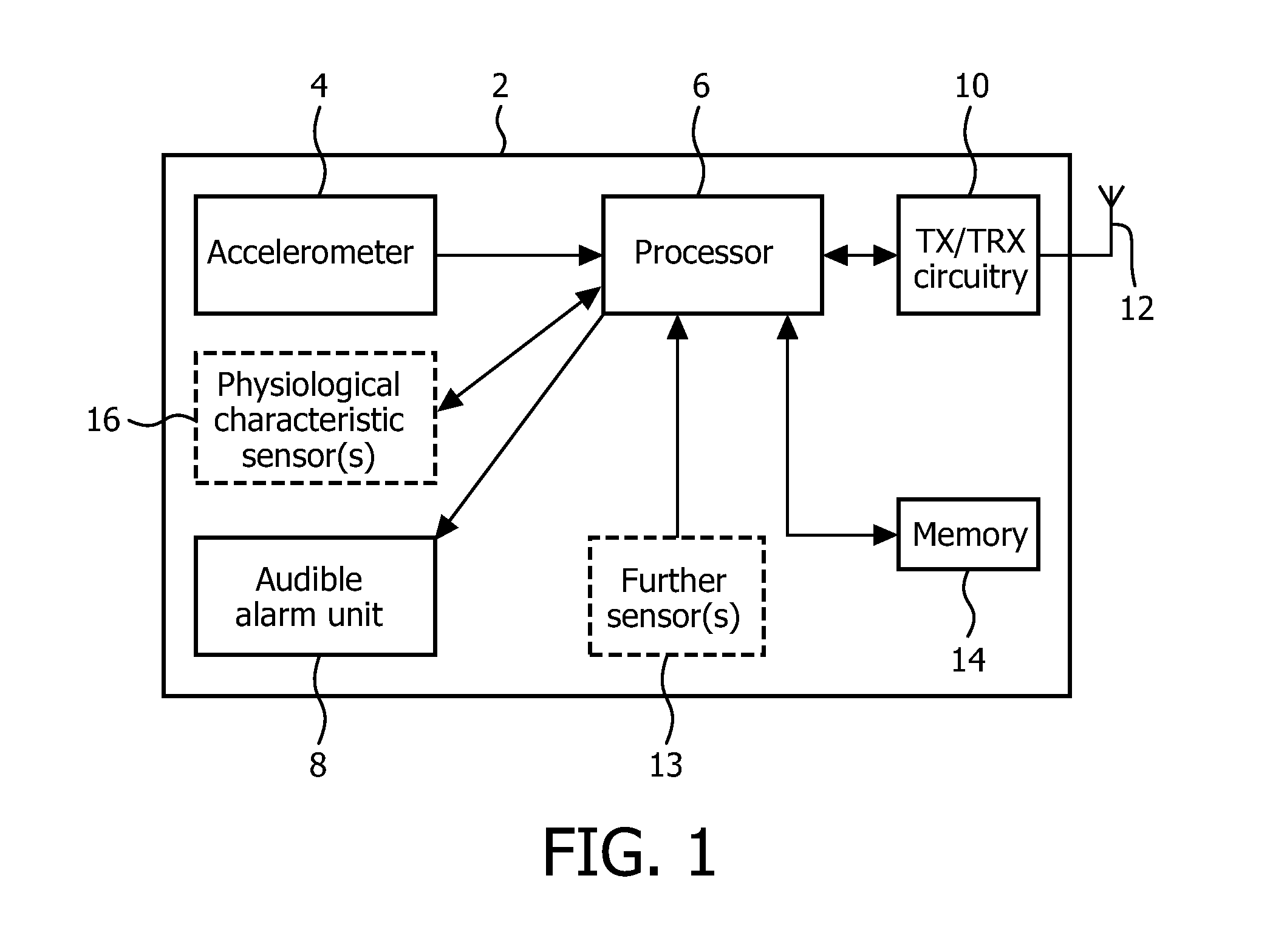
[0040]FIG. 1 illustrates an exemplary fall detector 2 in accordance with an embodiment of the invention. The fall detector 2 is in the form of a sensor unit that is to be worn by a user. The fall detector 2 can be provided in the form of a pendant with a neck cord for placement around the user's neck, but alternatively the fall detector 2 can be configured to be worn at or on a different part of the user's body, such as the wrist, waist, trunk, pelvis or sternum, and will comprise a suitable arrangement for attaching the fall detector 2 to that part of the body (for example a belt or a strap).

[0041]The fall detector 2 is used to measure the movement of the user (for example the accelerations experienced by the user) and to process the measurements to determine whether the user has fallen.

[0042]The fall detector 2 comprises a movement sensor 4 for measuring the movement of the user. The movement sensor 4 is preferably an accelerometer 4, and is preferably an accelerometer 4 that meas...


PUM


Abstract

There is provided a method of operating a fall detector, the method comprising, on detecting a fall event by a user of the fall detector, measuring at least one physiological characteristic of the user; and using the measurement of the at least one physiological characteristic to determine whether to expedite an alert that the user has fallen. An apparatus comprising a processor that is configured to perform the method described above is also provided.

Description

TECHNICAL FIELD OF THE INVENTION[0001]The invention relates to an apparatus for use in a fall detector or a fall detection system that detects falls by a user and triggers an alert when a fall occurs in order to get help for the user, and a method of operating the same.BACKGROUND TO THE INVENTION[0002]Falls affect millions of people each year and result in significant injuries, particularly among the elderly. In fact, it has been estimated that falls are one of the top three causes of death in elderly people. A fall is defined as a sudden, uncontrolled and unintentional downward displacement of the body to the ground or a lower level, followed by contact (such as an impact) with the ground or lower level, after which the body stays down on the ground.[0003]Personal Help Buttons (PHBs) are available that require the user to push the button to summon help in an emergency. When pressed, the PHB initiates a call to a call centre and then allows the user to communicate with call centre s...

Claims


Application Information

Patent Timeline
Patent Type & Authority Applications(United States)
IPC IPC(8): G08B21/02
CPCG08B21/02A61B5/0531G08B21/0446G08B21/0453A61B5/747A61B5/02055A61B5/021A61B5/02438A61B5/1102A61B5/14551A61B2562/0219H04M3/5116H04M2250/12A61B5/1117G08B21/04A61B5/1126A61B5/1116A61B5/11A61B5/7203A61B5/725A61B5/7275A61B5/7282
Inventor TEN KATE, WARNER RUDOLPH THEOPHILE
Owner KONINKLJIJKE PHILIPS NV
Learn More