Eureka AIR delivers breakthrough ideas for toughest innovation challenges, trusted by R&D personnel around the world.

Radio-frequency based catheter system and method for ablating biological tissues

a biological tissue technology, applied in the field of radio frequency based catheter systems for ablating biological tissues and occlusions, can solve the problems of a large health care burden, stroke and heart attack, and the inability to widely adopt maze procedures, so as to achieve efficient tissue ablation and minimize the effect of reflected power ratio

Inactive Publication Date: 2006-07-04
MEDWAVE INC
View PDF24 Cites 100 Cited by
  • Summary
  • Abstract
  • Description
  • Claims
  • Application Information

AI Technical Summary

Benefits of technology

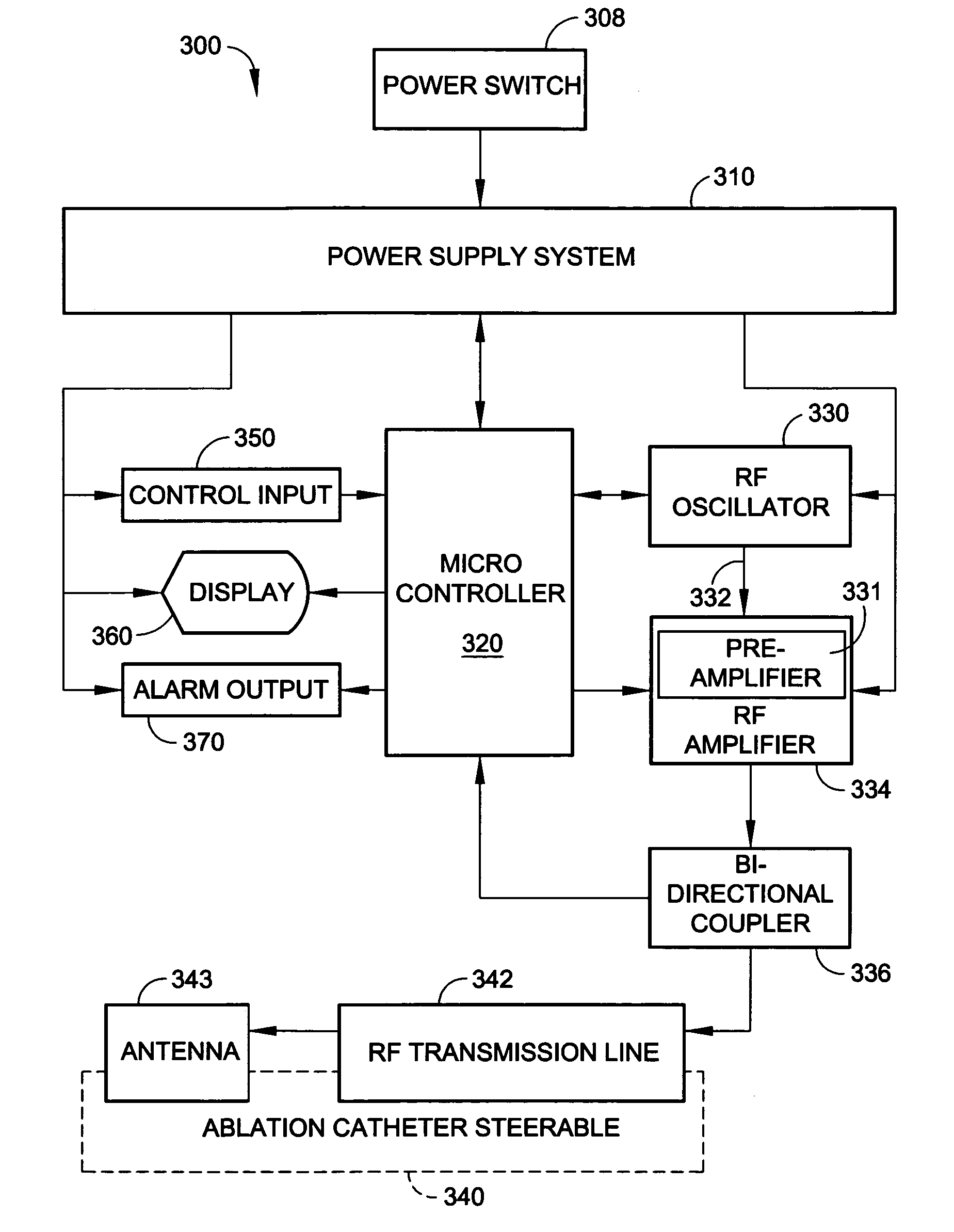
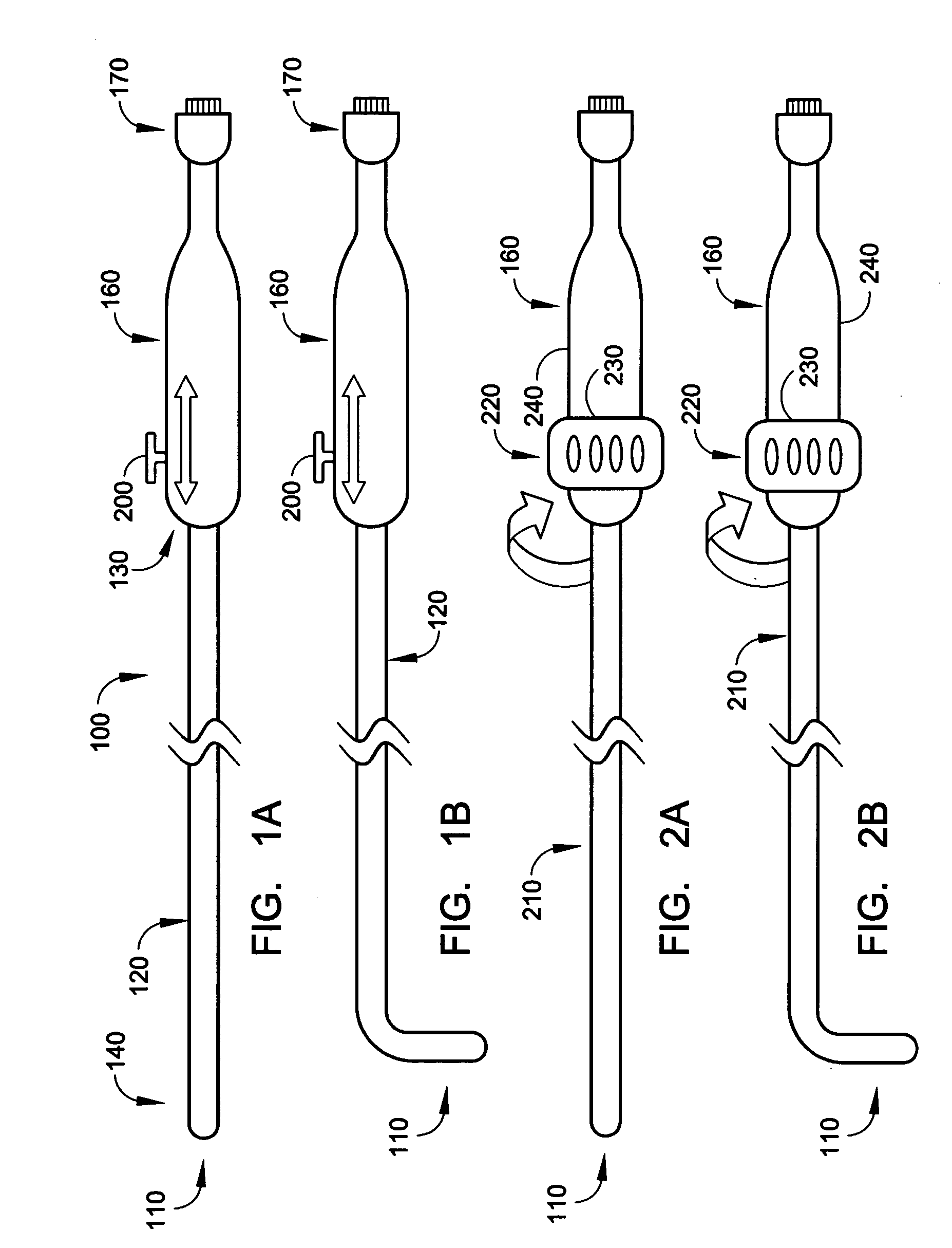
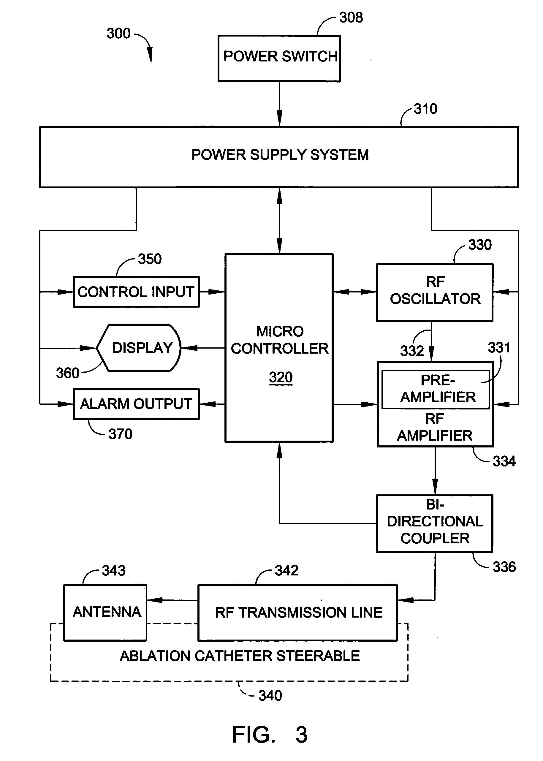
[0017]According to the present invention, an improved radio frequency based catheter system is provided for ablating biological tissues of a body vessel, including the atrium of a patient. The system comprises a RF generator in the microwave frequency range adapted for communicating RF energy to a catheter that is adaptable for insertion into the body vessel and a deflectable antenna guide disposed within the catheter lumen. The catheter comprises an RF transmission line and a deflectable RF antenna provided at the distal portion of the catheter to receive and transmit radio frequency energy for tissue ablation. The antenna includes a helical coil and has an axial passageway to accommodate the antenna guide, which, upon deployment prescribes the ablation pathway of the antenna for tissue ablation. In a representative embodiment of the invention, the antenna guide includes elongated portions that are secured to control slides for positioning and deployment and deflection control. Alignment of the antenna with the desired tissue ablation pathway is facilitated with the use of radio-opaque markers and an antenna element, which is radio-opaque. After the RF antenna is positioned within the body vessel, the RF generator is activated to apply energy to the antenna. The RF generator will monitor and minimize reflected to forward power ratio of the antenna and antenna-tissue interface by adjusting the microwave frequency for efficient tissue ablation.
[0019]After the RF antenna is positioned in the proximity of the body tissue within the body vessel, the RF generator is activated to apply energy to the antenna. The RF generator monitors and minimizes reflected to forward power ratio of the antenna and antenna-tissue interface by adjusting the microwave frequency for efficient tissue ablation.

Problems solved by technology

Despite these advances in technology, atrial fibrillation (“AF”) remains a significant challenge.
AF, a rapid irregular rhythm in the atria or upper chambers of the heart induced by non-uniformed electrical pulses, represents a leading cause of stroke and heart attack and a major health care burden.
However, the Maze procedure has not been widely adopted due to the morbidity and mortality associated with open-heart surgery, which involves the opening of the chest cavity and cutting of the chest bones.
In addition, during the ablation, disruption of cardiovascular function is reduced.
A major drawback of such existing procedures is the time-consuming task of positioning the catheter-electrode at the desired ablation spots within the atrium while the heart chamber muscles are pulsating.
Movements of the atrial wall or the heart muscles often render accurate placement of the catheter-electrode difficult, and slippage of the catheter-electrode tends to occur thereby damaging portions of the atrium where ablation is not desired.
As a result, placement of the catheter based RF ablation cannot be efficiently accomplished, and prolonged procedure time, in excess of 12 hours, can be expected.
As a result, such inconvenience is often amplified by the prolonged procedure time, which detracts from the use of a catheter-based electrode as an efficient means for tissue ablation.
However, while this design reduces the likelihood of antenna or catheter-electrode slippage during each ablation step, it does not eliminate the consuming task of securing precise placement of the antenna along the desired ablation path for each ablation step.

Method used


Image

  • Radio-frequency based catheter system and method for ablating biological tissues
  • Radio-frequency based catheter system and method for ablating biological tissues
  • Radio-frequency based catheter system and method for ablating biological tissues

Examples


Embodiment Construction

[0026]The present invention involves a radio-frequency based catheter system for the ablation of biological tissues, as shown in FIG. 1. In particular the present invention is adaptable to ablate tissues located in the internal vessels of living mammals by way of a radio-frequency (RF) antenna that is incorporated as part of a catheter. The catheter is insertable within the internal lumens or body vessels of such mammals and the RF antenna is placed in proximity of the tissues to be ablated where RF energy is applied to effect the tissue ablation.

[0027]The invention provides a means for generating a train of RF energy pulses, especially in the microwave frequency range, which are delivered via an electrical transmission line to the RF antenna. The frequency of the RF energy pulses can be selectively varied according to the electrical characteristics of the electrical transmission line and the load impedance associated with the tissue ablation.

[0028]The invention also incorporates a ...


PUM


Abstract

A method for biological tissue ablation includes shaping a shapeable RF antenna to accommodate the contour of a body vessel adjacent a biological tissue load; generating a train of radio frequency (RF) energy pulses at an output frequency for transmission in a transmission line to the shapeable RF antenna adjacent the biological tissue load; sensing a reflected signal and a forward signal of the RF energy pulses; and adjusting output frequency of the RF energy pulses to effect a substantial match of transmission line impedance with shapeable RF antenna and biological tissue load impedance.

Description

RELATED APPLICATIONS[0001]This application is a continuation-in-part of U.S. patent application Ser. No. 10 / 306,757, filed Nov. 27, 2002 now U.S. Pat. No. 7,004,938, which is a continuation-in-part of U.S. patent application Ser. No. 09 / 459,058, filed Dec. 11, 1999 now U.S. Pat. No. 6,663,625, which is continuation-in-part of U.S. patent application Ser. No. 09 / 211,188 filed Dec. 14, 1998, now U.S. Pat. No. 6,190,382.FIELD OF THE INVENTION[0002]The present invention concerns a Radio Frequency (RF) based catheter system for ablating tissue and occlusions, particularly within liquid-filled lumens of animals, such as heart, liver, arteries and vessels of a human, with an electrical field produced about an RF antenna. More particularly, the invention concerns an apparatus providing an impedance match between an electrosurgical electrode, such as an antenna, and its environs, by controllably adjusting the frequency to minimize RF energy reflection.BACKGROUND[0003]This invention relates g...

Claims


Application Information

Patent Timeline
IPC IPC(8): A61B18/04A61BA61B18/14
CPCA61B18/1492A61B18/18A61B19/54A61B2017/003A61B2018/1437A61B2018/00839A61B2018/00875A61B2018/1407A61B2018/00214A61B90/39
Inventor ORMSBY, THEODORE C.LAW, MING-FANLEUNG, GEORGE L.
Owner MEDWAVE INC
Why Eureka
Eureka Blog
Learn More