
Peak suppression method, peak suppression apparatus and wireless transmission apparatus
a technology of peak suppression and wireless transmission, applied in the field of peak suppression technique, can solve the problems of reducing the peak-to-average power ratio (papr) of the input signal, cutting off the original signal by a large amount, and increasing the circuit size, so as to reduce the output back-off, and improve the amplification efficiency
- Summary
- Abstract
- Description
- Claims
- Application Information
AI Technical Summary
Benefits of technology
Problems solved by technology
Method used
Image

Examples
first embodiment
[0048]The first description is of the case of changing over between a window function method and a clipping suppression method.
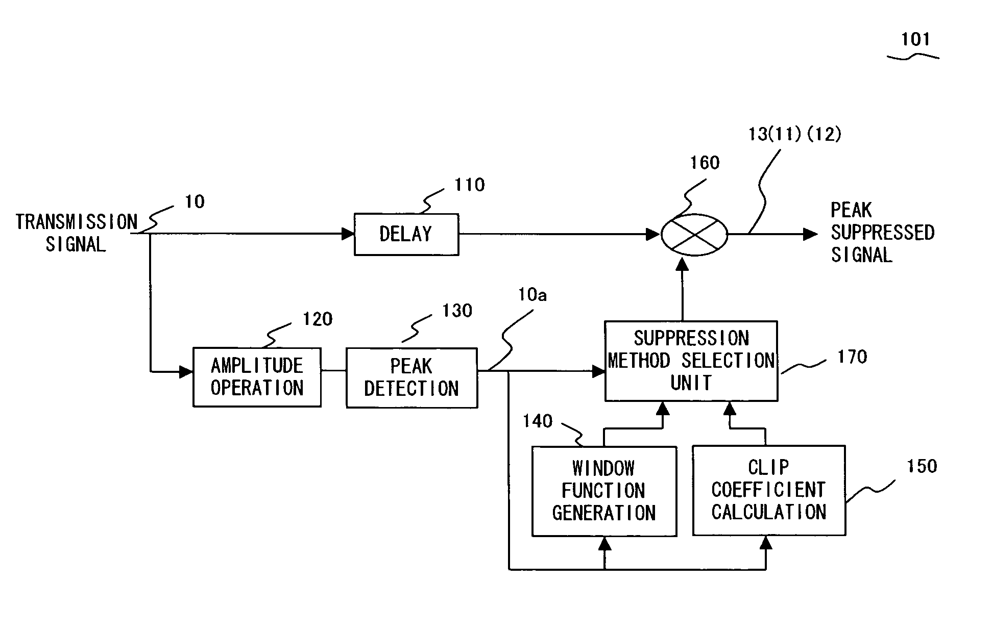
[0049]FIG. 3 is a conceptual diagram exemplifying a configuration of a peak suppression apparatus embodying a peak suppression method according to an embodiment of the present invention.
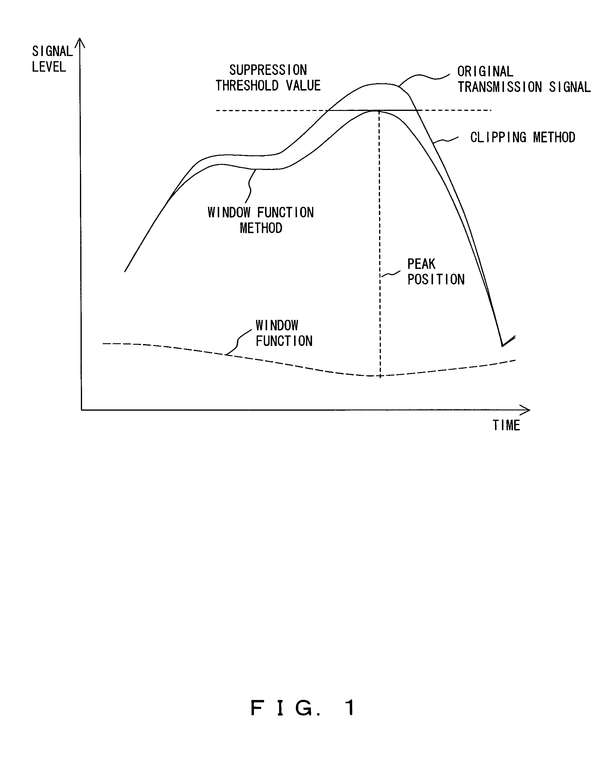
[0050]FIG. 4 is a graph exemplifying an operation of a configuration of a peak suppression apparatus embodying a peak suppression method according to an embodiment of the present invention.
[0051]The peak suppression apparatus 101 according to the present embodiment includes a delay buffer 110, an amplitude operation unit 120, a peak detection unit 130, a window function generation unit 140, a clip coefficient calculation unit 150, a multiplication unit 160 and a suppression method selection unit 170.
[0052]A transmission signal 10 is branched and input to the delay buffer 110 and amplitude operation unit 120. The delay buffer 110 inputs, to the multiplication unit 160, the tra...
second embodiment
[0095]The next description is of the case of changing a window width in a peak suppression method using the window function.
[0096]FIG. 11 is a block diagram exemplifying a configuration of a peak suppression apparatus 102 according to the present second embodiment.
[0097]Where the configuration shown by FIG. 11 differs from the configuration example shown by the above described FIG. 3 is that the former uses the window function generation unit 140 independently and also is equipped with a window function width determination unit 180 for controlling a window width in the aforementioned window function generation unit 140.
[0098]The window function width determination unit 180 variably controls a width W (refer to FIG. 4) of the window function at the window function generation unit 140 based on characteristic information 10a detected by the peak detection unit 130.
[0099]In a peak suppression by the window function, although the larger a width W of a multiplying window function the more...
third embodiment
[0112]The next description is of the case of controlling a plurality of window function methods.
[0113]FIG. 12 is a block diagram exemplifying a configuration of a peak suppression apparatus 103 according to the third embodiment.
[0114]The peak suppression apparatus 103 comprises a peak suppression stage S1 including a delay buffer 111, a multiplication unit 161, an amplitude operation unit 121, a peak detection unit 131, a suppression method determination unit 190 and a window function generation unit 141; and a peak suppression stage S2 including a delay buffer 112, a multiplication unit 162, an amplitude operation unit 122, a peak detection unit 132 and a window function generation unit 142.
[0115]The delay buffer 111 and delay buffer 112, the multiplication unit 161 and multiplication unit 162, the amplitude operation unit 121 and amplitude operation unit 122, the peak detection unit 131 and peak detection unit 132, and the window function generation unit 141 and window function ge...
PUM
 Abstract
Description
Claims
Application Information