Method and device for estimating carrier frequency offset

a carrier frequency offset and carrier frequency technology, applied in the field of carrier frequency offset estimation, can solve the problems of low snr error floor in cfo estimates, performance degradation when applied to two-way relaying, and standard preambles presently used for point-to-point transmissions or one-way relay transmissions cannot be readily applied to two-way relay transmissions

Inactive Publication Date: 2012-11-29
AGENCY FOR SCI TECH & RES
View PDF6 Cites 2 Cited by
  • Summary
  • Abstract
  • Description
  • Claims
  • Application Information

AI Technical Summary

Benefits of technology

[0016]selecting from the modulated plurality of combinations a selected signal of an optimal combination, the optimal combination minimizing the peak-to-average power ratio of the corresponding signal; wherein the selected signal is the time domain signal.

Problems solved by technology

However, since the spectral resources are shared, the signal communicated by any one source node is delivered not only across to the other source node, but also back to itself as an interference by way of the relay node.
Thus, standard preambles presently used for point-to-point transmissions or one-way relay transmissions may not be readily applied to two-way relay transmissions.
In this case however, an error floor in the CFO estimates is observed at high SNR due to the presence of inter-carrier-interference caused by the CFO.
Also, this strategy is designed for one-way relays and performance degrades when applied to two-way relaying.

Method used


Image

  • Method and device for estimating carrier frequency offset
  • Method and device for estimating carrier frequency offset
  • Method and device for estimating carrier frequency offset

Examples


Embodiment Construction

[0069]The following notations may be used in this specification. Boldfaces in capital and small letters respectively denote matrices and vectors. All indices in matrices and vectors start from zero unless otherwise stated. The symbol {circle around (×)} denotes a convolution. N(O,R) denotes a multivariate Gaussian distribution with a zero mean and with a covariance matrix R.

[0070]System Model

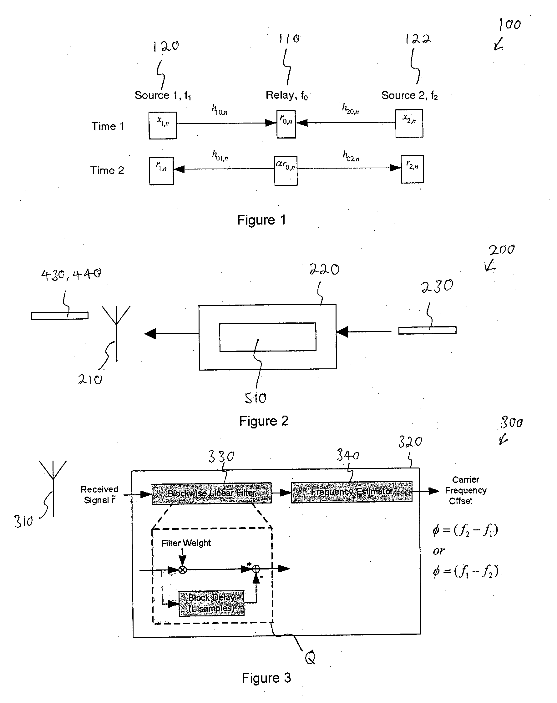
[0071]FIG. 1 shows a communications system 100 according to the preferred embodiment. The communications system 100 comprises a relay node 110 and two source nodes i.e. Source 1120 and Source 2122. The relay node 110 and the source nodes are each capable of two-way relay communications. In other words, Source 1120 is capable of transmitting to the relay node 110 and receiving from the relay node 110. Similarly, Source 2122 is also capable of transmitting to the relay node 110 and receiving from the relay node 110.

[0072]Variable SA denotes a node A while hAB denotes a channel from a node A to a n...


PUM


Abstract

A method (500) for estimating a carrier frequency offset in a communication system (100) is disclosed herein. In a described embodiment, the communications system (100) comprises a first communications device (120), a second communications device (122) and a relay (110). The method (500) comprises rotating (530) at the first communications device (120) a first generated block of signals by a first plurality of different rotation angles to form a corresponding first set of preambles (410), rotating (530) at the second communications device (122) a second generated block of signals by a second plurality of different rotation angles to form corresponding second set of preambles (420), transmitting (540) from each of the first and second communications devices (120,122) the respective first and second sets of preambles (410, 420) as time domain signals to the relay (110), receiving at the first communications device (120) a retransmitted time domain signal from the relay (110), the retransmitted signal being a combination of the first and second sets of preambles (410, 420) and estimating (550) the channel frequency offset based on the received retransmitted time domain signal. A device and an integrated circuit for estimating a carrier frequency offset in a communication system are also disclosed.

Description

FIELD OF THE INVENTION[0001]The present invention relates to a method and device for estimating carrier frequency offset, particularly but not exclusively for two-way relays.BACKGROUND OF THE INVENTION[0002]The technique of relaying for introducing cooperative diversity to wireless transmission has potential for throughput and range extension. In particular, two-way relays are an efficient network transmission scheme that is capable of supporting the exchange of data packets between two source nodes in only half the time required in one-way relays. In two-way relays, two source nodes send independent data streams using the same time slots and bandwidth. However, since the spectral resources are shared, the signal communicated by any one source node is delivered not only across to the other source node, but also back to itself as an interference by way of the relay node. Thus, consideration is given to interferences when designing preambles for frequency synchronization in two-way re...

Claims


Application Information

Patent Timeline
Patent Type & Authority Applications(United States)
IPC IPC(8): H04B7/14H04L12/26H04B17/40
CPCH04B7/155H04L27/262H04L27/2621H04L27/2657H04W88/04H04W24/00H04W56/0035H04W72/00H04L27/2692
Inventor FUNG, HO WANG PATRICKSUN, SUMEIHO, CHIN KEONG
Owner AGENCY FOR SCI TECH & RES
Why Eureka
Try Eureka