Peak suppression method, peak suppression apparatus and wireless transmission apparatus

a technology of peak suppression and wireless transmission, applied in the field of peak suppression technique, can solve the problems of reducing the peak-to-average power ratio (papr) of the input signal, cutting off the original signal by a large amount, and increasing the circuit size, so as to reduce the output back-off, and improve the amplification efficiency

Inactive Publication Date: 2007-09-20
FUJITSU LTD
View PDF60 Cites 10 Cited by
  • Summary
  • Abstract
  • Description
  • Claims
  • Application Information

AI Technical Summary

Benefits of technology

[0016] A purpose of the present invention is to provide a peak suppression technique capable of reducing an output back-off of a transmission amplifier by minimizing a Peak-to-Average Power ratio (PAPR) of a transmission signal, thereby improving amplification efficiency.
[0017] Another purpose of the present invention is to provide a peak suppression technique capable of minimizing a Peak-to-Average Power ratio (PAPR) of a transmission signal while effectively adjusting a balance between a degradation of a reception characteristic and a degradation of a distortion characteristic due to the peak suppression.
[0018] Yet another purpose of the present invention is to provide a peak suppression technique capable of accomplishing an optimization of a balance between a reception characteristic and a distortion characteristic in a peak suppression signal of a transmission signal responding to characteristics of the aforementioned transmission signal generated by various modulation methods used for a wireless telecommunication apparatus.
[0024] This contrivance makes it possible to have a balance between a reception characteristic and a distortion characteristic approach the most optimal point.
[0025] An application of the present invention to a peak part of a transmission signal used for a digital wireless telecommunication, et cetera, makes it possible to minimize a Peak-to-Average Power ratio (PAPR) of an input signal to a transmission amplifier, reduce an output back-off thereof and improve amplification efficiency.
[0026] The present invention further makes it possible to accomplish an optimization of a balance between a reception characteristic and a distortion characteristic in a peak suppressed signal of a transmission signal responding to characteristics of transmission signals provided by various modulation methods used for a wireless telecommunication apparatus.

Problems solved by technology

On the other hand, high frequency components are generated because the ends of the suppression are not smooth, thereby degrading a spectrum characteristic (i.e., a distortion characteristic).
For preventing this, a common method is a parallel use of a low pass filter (LPF) which, however, is faced with a technical problem of increasing a circuit size for including the LPF and of reproducing the once clipped peak as a result of the filtering.
In this case, a degradation of a spectrum characteristic is comparably smaller than the case of only using the clipping method because the ends of a suppression range can be relatively smoother, which, however, requires a multiplication of a window having a long time-width to some extent by an original signal, resulting in cutting that much signal off the original signal and an accordingly great degradation of the reception characteristic.
The technique disclosed by the patent document 1, using only the window function for carrying out the suppression, cannot solve the above described technical problem which is specific to the window function.

Method used


Image

  • Peak suppression method, peak suppression apparatus and wireless transmission apparatus
  • Peak suppression method, peak suppression apparatus and wireless transmission apparatus
  • Peak suppression method, peak suppression apparatus and wireless transmission apparatus

Examples


first embodiment

[0048] The first description is of the case of changing over between a window function method and a clipping suppression method.

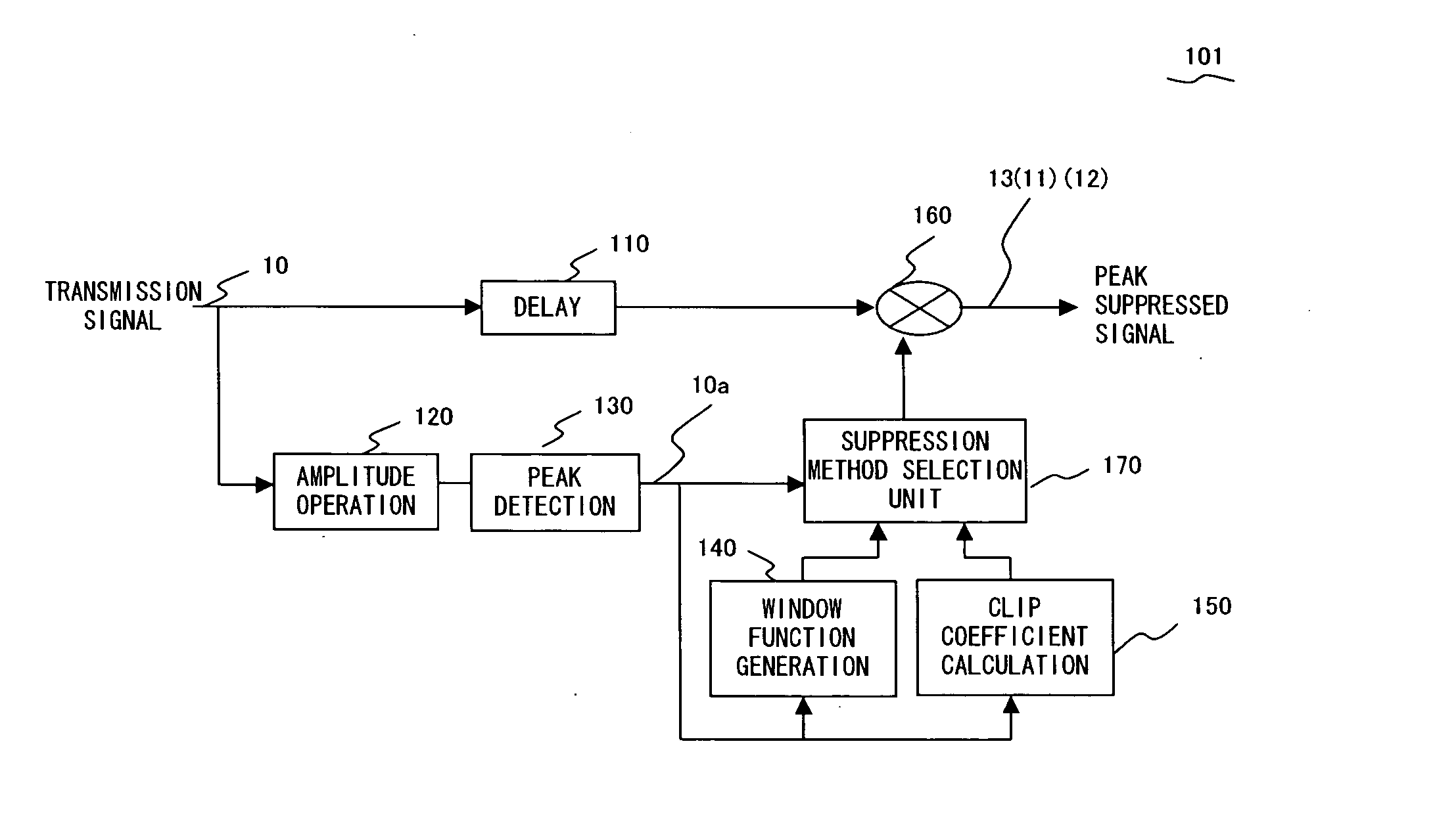
[0049]FIG. 3 is a conceptual diagram exemplifying a configuration of a peak suppression apparatus embodying a peak suppression method according to an embodiment of the present invention.

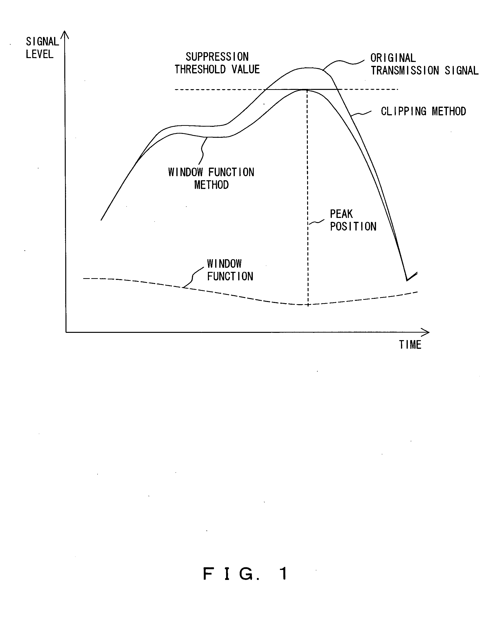
[0050]FIG. 4 is a graph exemplifying an operation of a configuration of a peak suppression apparatus embodying a peak suppression method according to an embodiment of the present invention.

[0051] The peak suppression apparatus 101 according to the present embodiment includes a delay buffer 110, an amplitude operation unit 120, a peak detection unit 130, a window function generation unit 140, a clip coefficient calculation unit 150, a multiplication unit 160 and a suppression method selection unit 170.

[0052] A transmission signal 10 is branched and input to the delay buffer 110 and amplitude operation unit 120. The delay buffer 110 inputs, to the multiplication unit 160, ...

second embodiment

[0094] The next description is of the case of changing a window width in a peak suppression method using the window function.

[0095]FIG. 11 is a block diagram exemplifying a configuration of a peak suppression apparatus 102 according to the present second embodiment.

[0096] Where the configuration shown by FIG. 11 differs from the configuration example shown by the above described FIG. 3 is that the former uses the window function generation unit 140 independently and also is equipped with a window function width determination unit 180 for controlling a window width in the aforementioned window function generation unit 140.

[0097] The window function width determination unit 180 variably controls a width W (refer to FIG. 4) of the window function at the window function generation unit 140 based on characteristic information 10a detected by the peak detection unit 130.

[0098] In a peak suppression by the window function, although the larger a width W of a multiplying window function ...

third embodiment

[0110] The next description is of the case of controlling a plurality of window function methods.

[0111]FIG. 12 is a block diagram exemplifying a configuration of a peak suppression apparatus 103 according to the third embodiment.

[0112] The peak suppression apparatus 103 comprises a peak suppression stage S1 including a delay buffer 111, a multiplication unit 161, an amplitude operation unit 121, a peak detection unit 131, a suppression method determination unit 190 and a window function generation unit 141; and a peak suppression stage S2 including a delay buffer 112, a multiplication unit 162, an amplitude operation unit 122, a peak detection unit 132 and a window function generation unit 142.

[0113] The delay buffer 111 and delay buffer 112, the multiplication unit 161 and multiplication unit 162, the amplitude operation unit 121 and amplitude operation unit 122, the peak detection unit 131 and peak detection unit 132, and the window function generation unit 141 and window funct...


PUM


Abstract

The present invention provides a peak suppression method, including a first step for detecting characteristic information of a peak part of a transmission signal; and a second step for changing a suppression method for the peak part based on the characteristic information.

Description

BACKGROUND OF THE INVENTION [0001] 1. Field of the Invention [0002] The present invention relates to a peak suppression technique, and to a technique effectively applicable to a peak suppression technique, et cetera, for an input signal to a transmission amplifier for use in a digital wireless telecommunication, et cetera for example. [0003] 2. Description of the Related Art [0004] A linear amplification is required to a transmission amplifier for use in the currently practiced major digital wireless telecommunication systems. [0005] Meanwhile, in a multi-carrier telecommunication system such as the Orthogonal Frequency Division Multiple Access (OFDM) system, a known fact is that a high peak power is often generated at the time of synthesizing a transmission signal. [0006] Generally, as a Peak-to-Average Power Ratio (PAPR) becomes large, a back-off power of a transmission amplifier needs to be large so as to operate it in a linear range, resulting in degrading an efficiency of the t...

Claims


Application Information

Patent Timeline
Patent Type & Authority Applications(United States)
IPC IPC(8): H04L25/03
CPCH04L27/2624
Inventor HAMADA, HAJIMEKUBO, TOKURONAGATANI, KAZUOISHIKAWA, HIROYOSHIFUDABA, NOBUKAZU
Owner FUJITSU LTD
Why Eureka
Try Eureka