Card edge connector, card type module, and connector

a card type module and connector technology, applied in the direction of coupling device connection, coupling parts engagement/disengagement, incorrect coupling prevention, etc., can solve the problems of stubs, adversely affecting high speed transmission, and branched portions at contact points

Inactive Publication Date: 2014-07-10
FUJITSU COMPONENENT LTD
View PDF2 Cites 4 Cited by
  • Summary
  • Abstract
  • Description
  • Claims
  • Application Information

AI Technical Summary

Problems solved by technology

However, this may cause the generation of branched portions at the contact points (a stub) formed by the pads and the conta

Method used


Image

  • Card edge connector, card type module, and connector
  • Card edge connector, card type module, and connector
  • Card edge connector, card type module, and connector

Examples


second embodiment

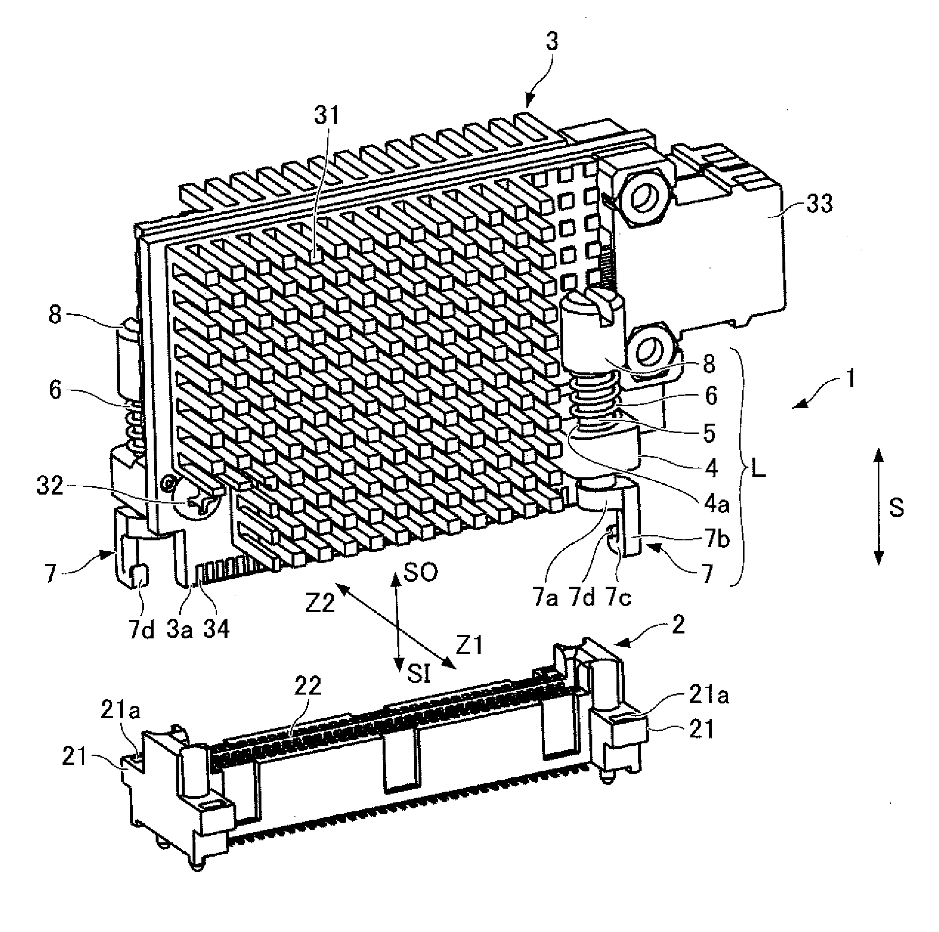
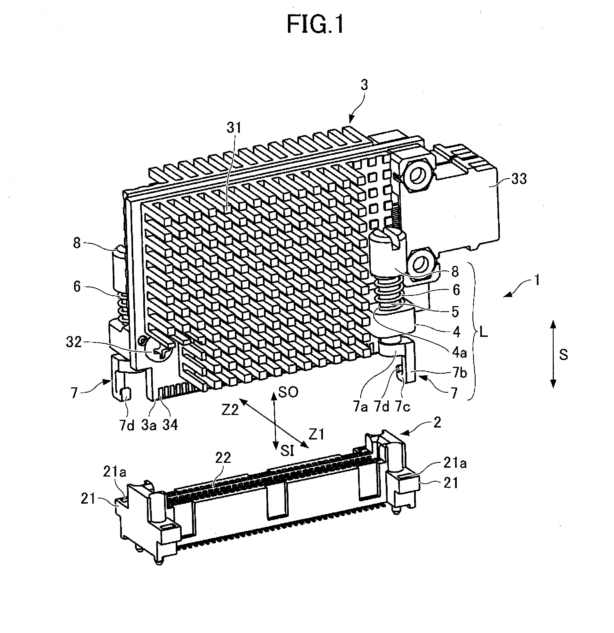
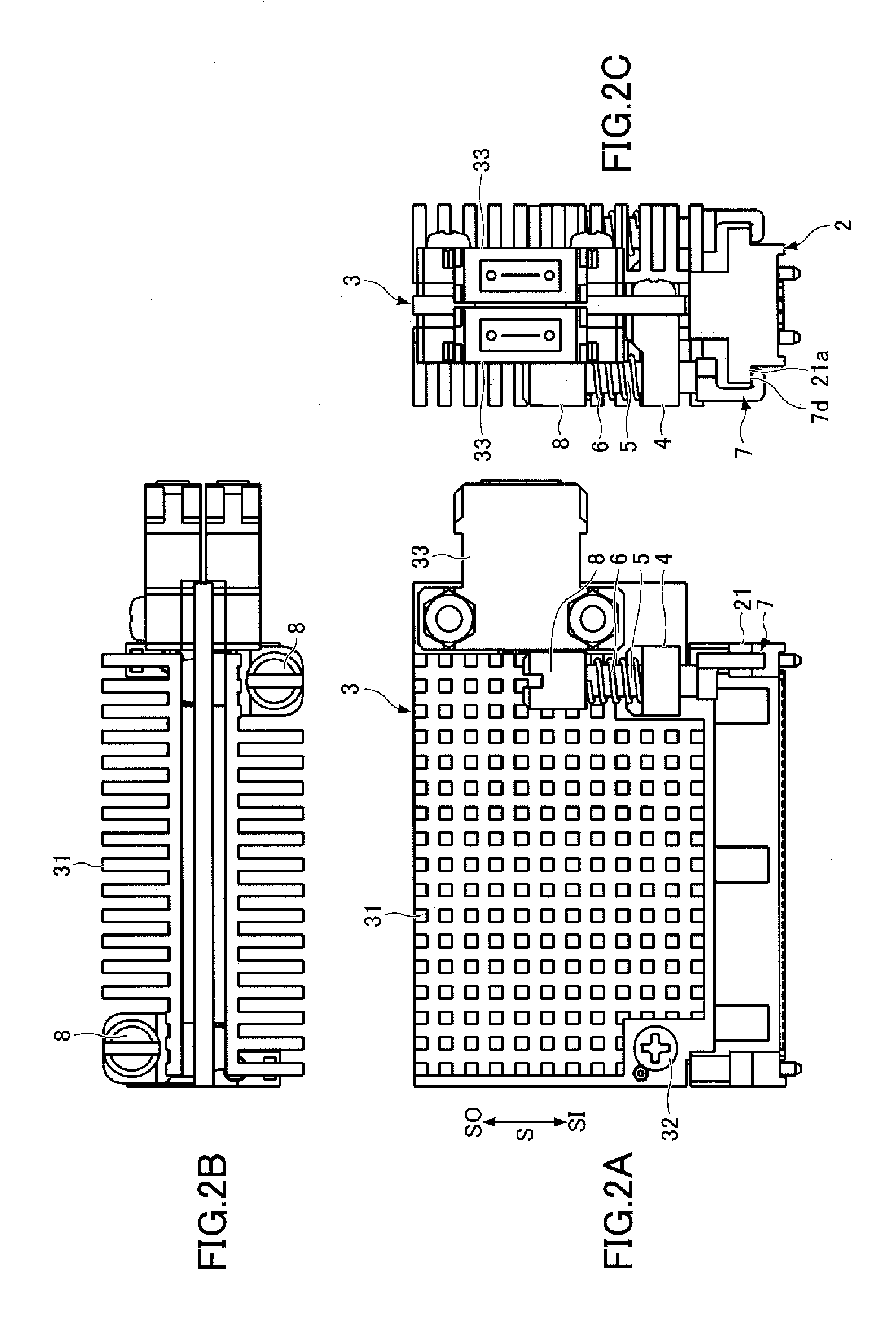
[0044]In the first embodiment, the lock 7 includes the radial part 7a, the axial part 7b, and the tangential part 7c formed in this order from the side that the shaft 5 is provided. However, this order may be arbitrarily changed as described in the following second embodiment.

[0045]Because the configuration of a card edge connector of the second embodiment illustrated in FIG. 10 is substantially the same as the above-described configuration of the first embodiment except for a lock 17, the differences between the first and second embodiments are mainly described below. The lock 17 of the second embodiment includes an axial part 17a having a diameter greater than a diameter of the shaft 5, a radial part 17b, and a tangential part 17c. Similar to the lock 7d of the first embodiment, the lock 17 may also include a protruding part 17d to be inserted to the recess 21a of the target engagement part 21.

[0046]The axial part 17a, the radial part 17b, and the tangential part 17c of the lock 1...


PUM


Abstract

A card edge connector includes a connector including a target engagement part, a substrate that can be inserted into and removed from the connector, a fixing part fixed to the substrate, and a lock that secures the substrate to the connector. The lock includes a shaft fixed to the fixing part and configured to slide in the direction of insertion and removal of the substrate and rotate around an axis, an urging part that exerts force on the shaft and biasing the shaft toward the direction of the substrate, and an engagement part provided on the shaft, configured to engage the target engagement part.

Description

CROSS-REFERENCE TO RELATED APPLICATIONS[0001]This application is based upon and claims the benefit of priority of the prior Japanese Patent Application No. 2013-002045 filed on Jan. 9, 2013, the entire contents of which are hereby incorporated by reference.BACKGROUND[0002]1. Field of the Invention[0003]The present invention generally relates to a card edge connector including a substrate having pads provided on its end part (card edge) and a connector having contacts corresponding to the pads, a substrate used for the card edge connector, and a connector used for the card edge connector.[0004]2. Description of the Related Art[0005]A conventional card edge connector includes multiple conductive contacts arranged in parallel on the sides of a connector, multiple insulators for containing the contacts, and a substrate corresponding to the connector that includes multiple conductive pads corresponding to the multiple conductive contacts. A card edge connector disclosed in Japanese Laid-...

Claims


Application Information

Patent Timeline
IPC IPC(8): H01R13/621
CPCH01R13/621H01R12/00H01R12/721H01R13/635
Inventor MIKI, YASUYUKIKOBAYASHI, MITSURU
Owner FUJITSU COMPONENENT LTD
Why Eureka
Try Eureka