
Vehicle, and control method and control apparatus for an automatic transmission

a technology of automatic transmission and control method, which is applied in the direction of mechanical apparatus, digital data processing details, instruments, etc., can solve the problems of delay in disengaging the engagement and delay in shifting the gear

Inactive Publication Date: 2010-04-22
TOYOTA JIDOSHA KK
View PDF10 Cites 2 Cited by
  • Summary
  • Abstract
  • Description
  • Claims
  • Application Information

AI Technical Summary

Benefits of technology

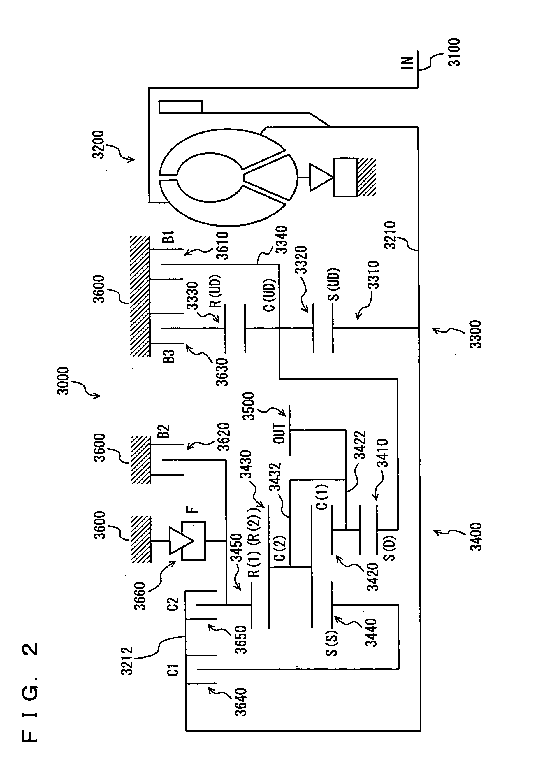
[0008]According to this configuration, a gear of a first gear ratio is implemented when a first engagement element and a second engagement element both engage. A gear of a second gear ratio is implemented when the second engagement element and a third engagement element both engage. A gear of a third gear ratio is implemented when the third engagement element and a fourth engagement element both engage. If a decision is made that shifting from the gear of the third gear ratio to the gear of the first gear ratio is to be done, the fourth engagement element is controlled to disengage and the third engagement element is controlled to have engagement force before the first engagement element and the second engagement element engage. Thus one of the two engagement elements implementing a gear before shifting can be disengaged and only the other can have engagement force. By disengaging one engagement element, shifting the gear can be started fast. Thus, shifting the gear can be started faster than when the state of one of two engagement elements disengaged as the gear is shifted is controlled in accordance with that of the other. Thus the gear can be shifted fast.
[0010]According to this configuration, the second engagement element is engaged when an input shaft of the automatic transmission attains a speed equal to a synchronous speed of the input shaft of the automatic transmission associated with the gear of the second gear ratio during shifting from the gear of the third gear ratio to the gear of the first gear ratio. Thus when the input shaft attains a speed equal to the synchronous speed of the input shaft associated with the gear of the second gear ratio can be matched to when an engagement element engaged when the gear of the second gear ratio is implemented has engagement force. This can reduce shock caused in shifting gears.
[0014]According to this configuration, the automatic transmission is provided with a rotating member having its rotation restricted by the engagement force of the third engagement element. A target value is set for the engagement force of the third engagement element in accordance with inertia of the rotating member. If shifting from the gear of the third gear ratio to the gear of the first gear ratio is to be done then before the first engagement element and the second engagement element engage the fourth engagement element disengages and the engagement force of the third engagement element is set to have the target value as set. This can reduce the third engagement element's engagement force for example to a minimal engagement force that can counter the rotating member's inertial force, i.e., a minimal engagement force that can restrict the rotating member's rotation. Thus the rotating member can be prevented from rotating at excessive speed while a gear is shifted, and when the third engagement element disengages it can disengage fast. As a result, the automatic transmission's input shaft, which is coupled with the rotating member, can be prevented from rotating at excessive speed, and such shock that can be caused when a gear is shifted can thus be reduced, and shifting a gear can proceed fast.
[0016]According to this configuration, if the gear of the third gear ratio is shifted to the gear of the first gear ratio, then before the first engagement element and the second engagement element engage the fourth engagement element is disengaged and the engagement force of the third engagement element is set to have the target value as set, and until the second engagement element engages the engagement force of the third engagement element is held at the target value as set. The third engagement element's engagement force decreased for example to a minimal engagement force that can restrict the rotating member's speed can be maintained until the second engagement element is engaged. This can reduce shock that can be caused when the second engagement element engages.
[0020]According to this configuration, when the automatic transmission's input shaft increases in speed at a large rate it can be said that the rotating member's inertial force is larger than when the input shaft increases in speed at a small rate. Accordingly, a larger target value is set for the third engagement element's engagement force. Thus for larger inertial force of the rotating member, the third engagement element's engagement force can be increased to be larger. This can prevent the rotating member's inertial force from being excessive while a gear is shifted.

Problems solved by technology

This delays disengaging the engagement elements implementing the gear having been implemented before shifting.
This may result in a delay in shifting the gear.

Method used


Image

  • Vehicle, and control method and control apparatus for an automatic transmission
  • Vehicle, and control method and control apparatus for an automatic transmission
  • Vehicle, and control method and control apparatus for an automatic transmission

Examples


Embodiment Construction

[0031]An embodiment of the present invention will be described hereinafter with reference to the drawings. In the following description, identical elements are denoted by identical reference characters. Their names and functions are also identical. Accordingly, they will not be described repeatedly in detail.

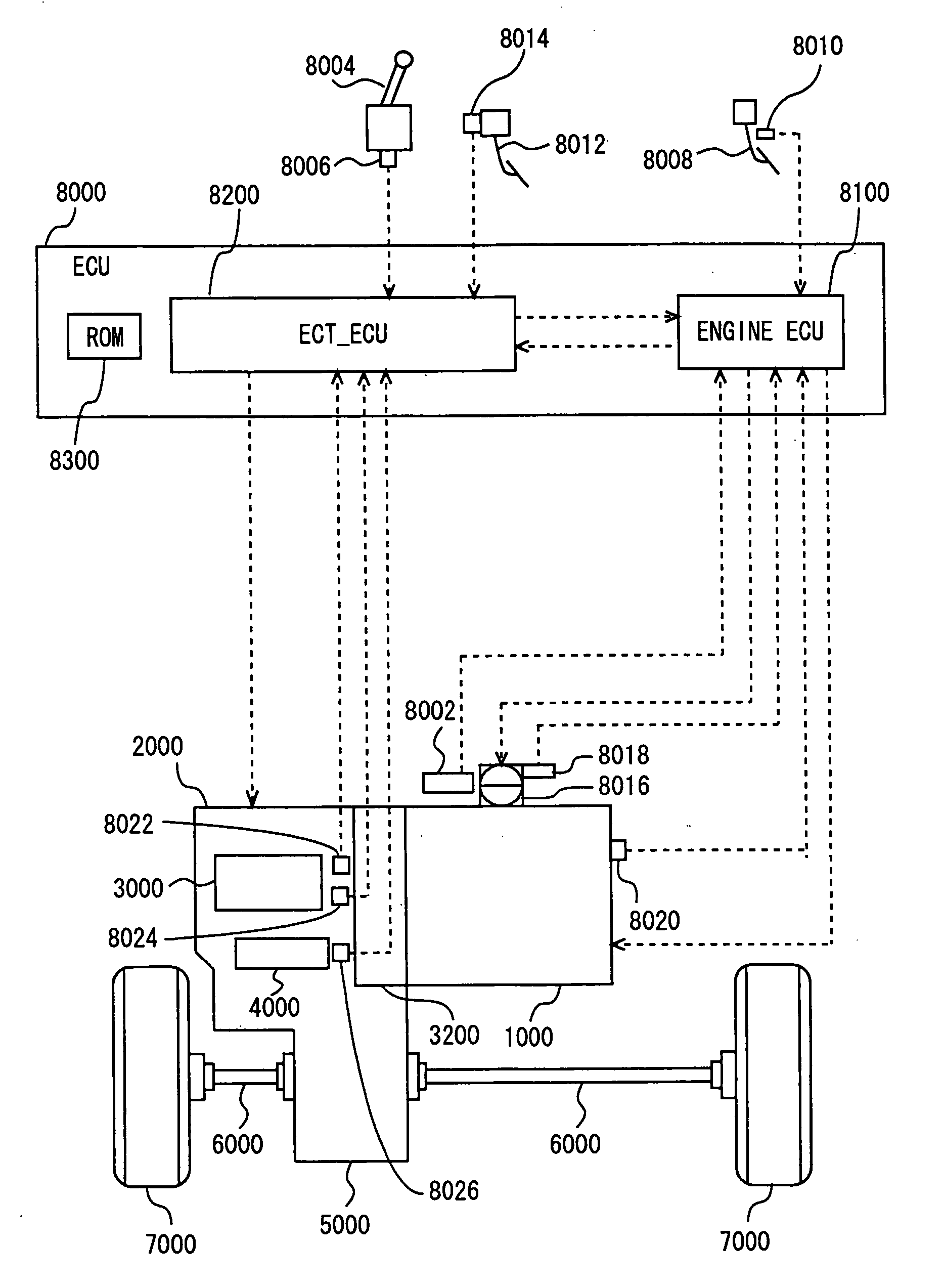
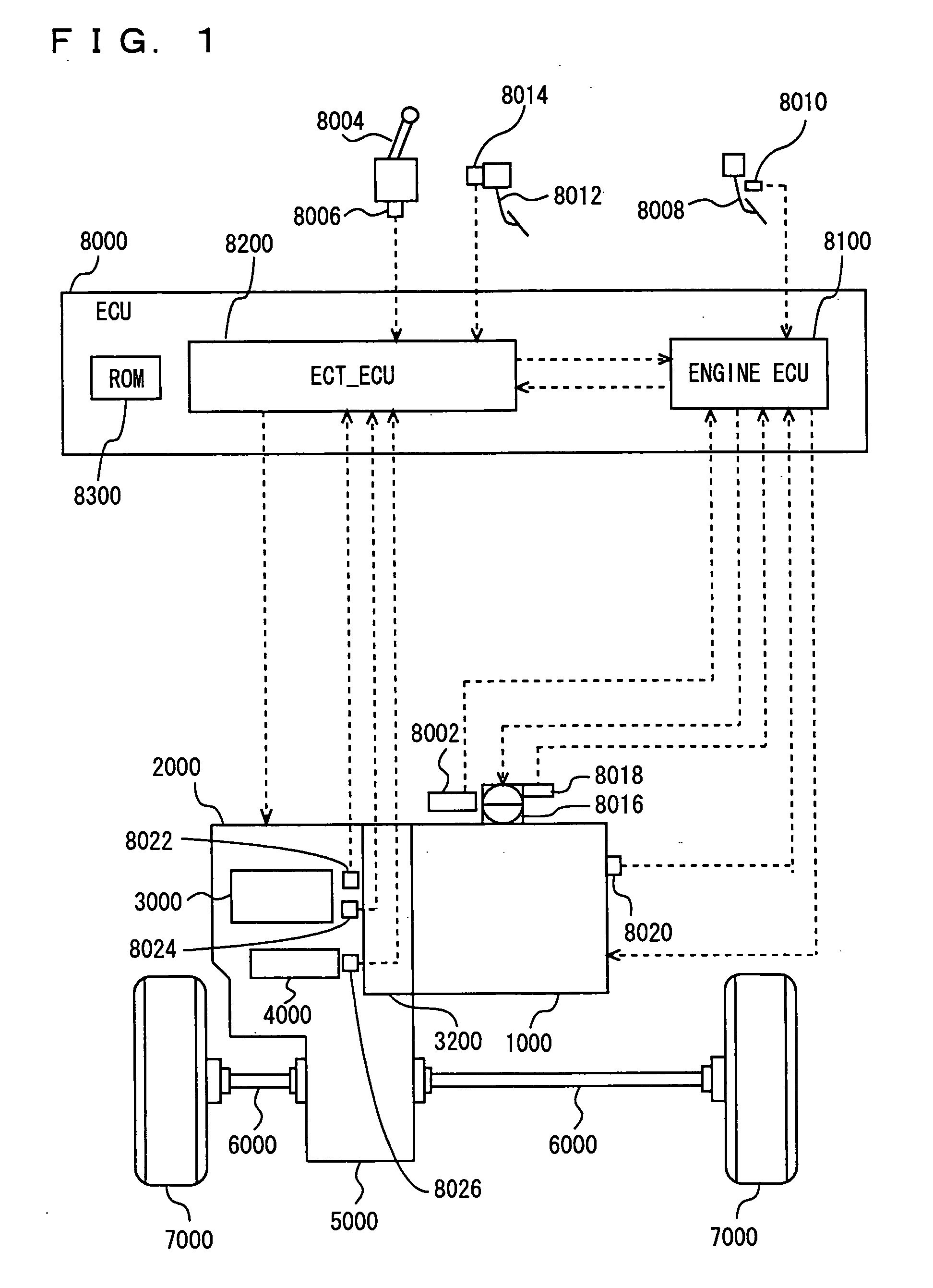
[0032]A vehicle incorporating a control apparatus according to an embodiment of the present invention will be described with reference to FIG. 1. The vehicle is an FF (front engine front drive) vehicle. It is not limited to the FF vehicle.

[0033]The vehicle includes an engine 1000, an automatic transmission 2000, a planetary gear unit 3000 constituting a portion of automatic transmission 2000, an oil hydraulic circuit 4000 constituting a portion of automatic transmission 2000, a differential gear 5000, a drive shaft 6000, a front wheel 7000, and an ECU (electronic control unit) 8000. In the present embodiment the control apparatus is implemented for example by executing a program...


PUM


Abstract

An ECU executes a program including the steps of: if downshift from a fifth gear implemented when a brake and a clutch both engage to a second gear implemented when a clutch and a brake both engage is done, or downshift from a sixth gear implemented when the brake and the clutch both engage to a third gear implemented when the clutch and the brake both engage is done, disengaging a frictional engagement element other than the clutch, i.e., the brake or the brake; and decreasing an engagement pressure that is applied to the clutch to a reference value of target engagement pressure.

Description

TECHNICAL FIELD[0001]The present invention relates to vehicles, and methods and apparatuses for controlling automatic transmissions, and particularly to technology applied to control engagement elements for implementing gears.BACKGROUND ART[0002]Conventionally there has been known an automatic transmission changing a combination of clutches, brakes and other similar engagement elements that engage to another combination thereof to shift gears. Such an automatic transmission may be required to shift from a gear implemented by engaging any two of a plurality of engagement elements to a gear implemented by engaging other different two of the plurality of engagement elements.[0003]Japanese Patent Laying-Open No. 2002-195401 discloses a shift control device for an automatic transmission that requires four engagement elements to operate to shift from a first gear to a second gear and the first gear is achieved when a first engagement element and a second engagement element both engage and...

Claims


Application Information

Patent Timeline
IPC IPC(8): G06F19/00F16H61/04F16H59/42F16H59/48F16H61/68F16H61/684F16H61/686
CPCF16H61/04F16H61/06F16H2306/14F16H2061/0455F16H2061/0451
Inventor FUKUSHIRO, EIJIOSHIMA, KOJI
Owner TOYOTA JIDOSHA KK
Learn More