Outer type antenna structure

Inactive Publication Date: 2014-07-17
OWITEK TECH
View PDF0 Cites 0 Cited by
  • Summary
  • Abstract
  • Description
  • Claims
  • Application Information

AI Technical Summary

Benefits of technology

The invention provides an outer type antenna structure that can be integrated with a connector, which solves the issue of conventional portable electrically communicative devices having limited antenna placement. This makes it easy to distribute the antennas, reducing signal interference among them.

Problems solved by technology

The location of the antenna arranged in the portable electrically communicative device may be limited so that the proper distribution of the antennas becomes difficult.
Therefore, the signal interference among the antennas can be increased.

Method used


Image

  • Outer type antenna structure
  • Outer type antenna structure
  • Outer type antenna structure

Examples


first embodiment

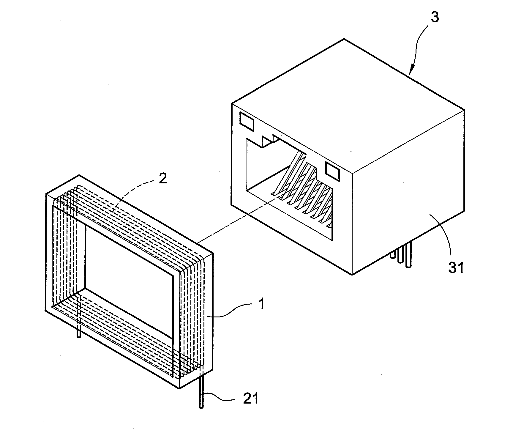
[0023]Please refer to FIG. 1. FIG. 1 schematically shows a perspective view of an outer type antenna structure of the invention. As shown in FIG. 1, the invention provides an outer type antenna structure including a frame 1 and an antenna 2.

[0024]The frame 1 may be material of plastics or rubbers. The frame may further include ferrite or steel which is used as an absorber for absorbing an emitting electric wave. The steel is preferred to have a high permeability. The frame 1 may surround outside of a connector (not shown in the drawings) or attach on a rim panel of an opening of the connector. Moreover, the frame 1 has a shape directed to the outer shape of the connector.

[0025]The antenna 2 may be a metallic wire or low temperature co-fired multi-layer ceramic. The antenna 2 may be buried in the frame 1 by a winding or a plurality of segments. The antenna 2 may extend to have at least one pin 21 outside of the frame 1.

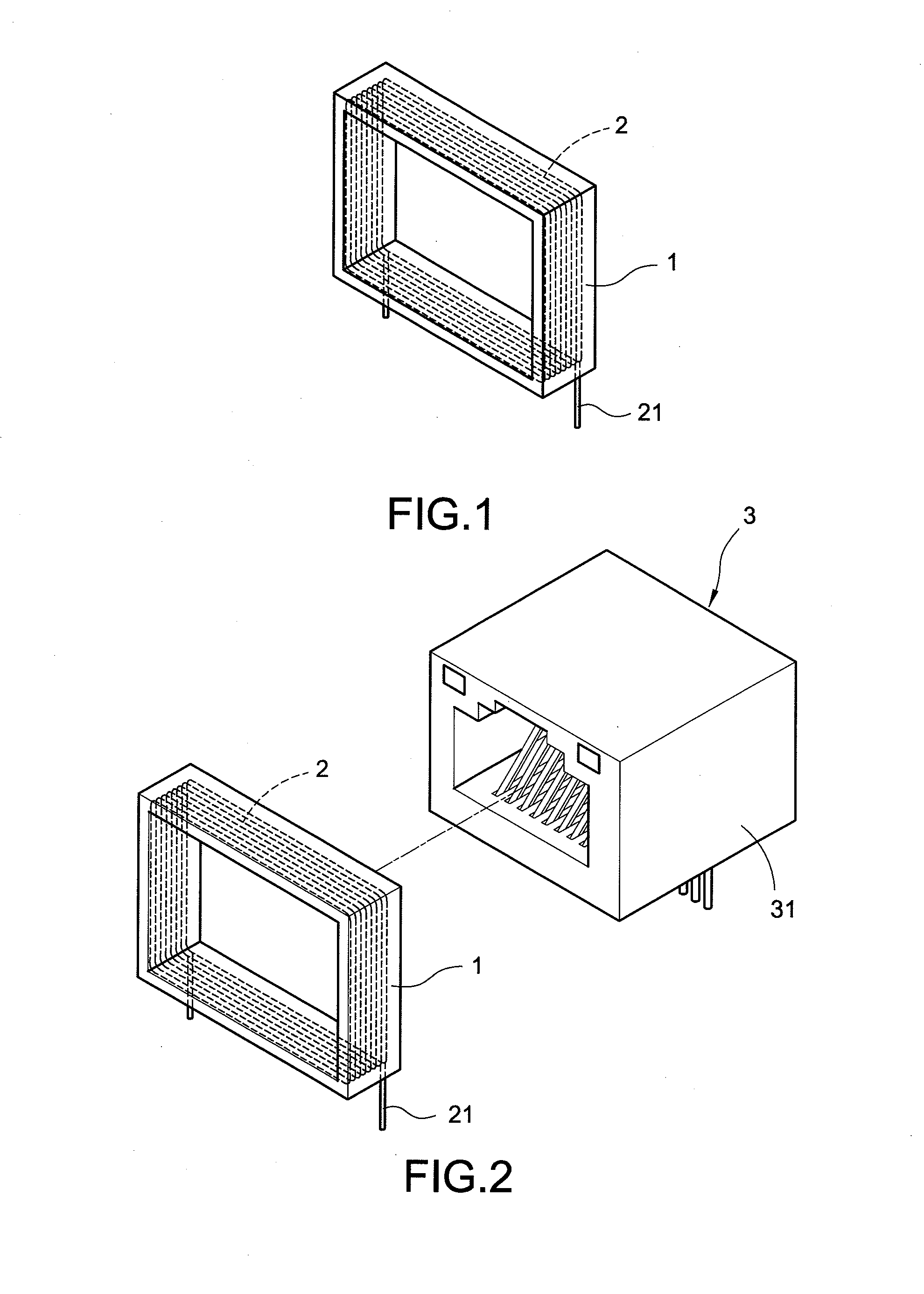
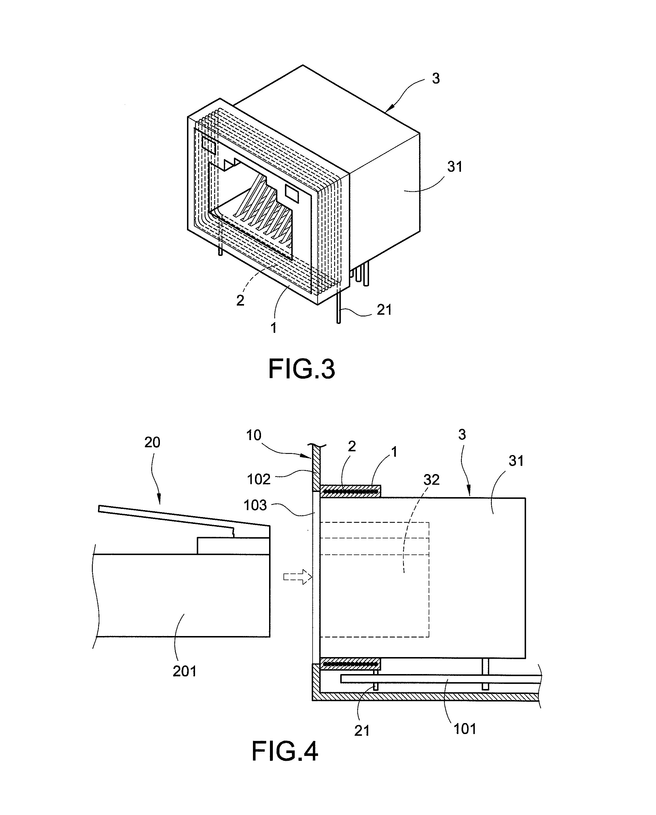
[0026]Please refer to FIGS. 2 and 3. FIGS. 2 and 3 respectively s...

third embodiment

[0032]Please refer to FIG. 7. FIG. 7 schematically shows an integration of an outer type antenna structure and a connector of the invention. As shown in FIG. 7, the integration of the outer type antenna structure and the connector 4 having a plastic housing 41 is completed by mold injection. The antenna 2 is buried in a mold when the mold injection of the plastic housing 41 is performed. The antenna 2 is enveloped in the plastic housing 41 when the mold injection is completed. When the connector 4 is electrically connected to an electronic device (not shown in FIG. 7), the pin 21 extending to outside of the plastic housing 41 is electrically connected to a circuit board of the electronic device.

fourth embodiment

[0033]Please refer to FIG. 8. FIG. 8 schematically shows an integration of an outer type antenna structure and a connector of the invention. As shown in FIG. 8, the integration of the outer type antenna structure and the connector 4 having a plastic housing 41 is completed by mold injection. The antenna 2 of a winding or a plurality of segments is buried in a mold when the mold injection of the plastic housing 41 is performed. The antenna 2 is enveloped in a frame 42 arranged on a rim of an opening of the plastic housing 41 when the mold injection is completed. When the connector 4 is electrically connected to an electronic device (not shown in FIG. 7), the pin 21 extending to outside of the frame 42 is electrically connected to a circuit board of the electronic device.

[0034]Please refer to FIGS. 9 and 10. FIG. 9 schematically shows a disconnected state of an outer type antenna structure and a connector of a fifth embodiment of the invention. FIG. 10 schematically shows a cross-sect...


PUM


Abstract

The invention relates to an outer type antenna structure comprising: a frame; an antenna arranged in the frame, the antenna extending to have a pin outside of the frame; and a connector. The antenna is integrated to the connector. The location of the antenna arranged in the portable electrically communicative device may be not limited so that the distribution of the antennas becomes easy. Therefore, the signal interference among the antennas can be reduced.

Description

BACKGROUND OF THE INVENTION[0001]1. Field of the Invention[0002]The present invention relates to an antenna, and more in particular, to an outer type antenna structure which can integrate to a connector.[0003]2. Related Art of the Invention[0004]Currently, the portable electrically communicative device is widely applied in a various fields. The portable electrically communicative device may provide users various functions of wireless internet, digital television, FM radio broadcast, navigation and positioning. However, in order to achieve the various functions of wireless internet, digital television, FM radio broadcast, navigation and positioning, the portable electrically communicative device have to be arranged a plurality of antennas therein.[0005]The portable electrically communicative device is directed to be miniaturized, so that the space between housing and a circuit board of the device is finite. The location of the antenna arranged in the portable electrically communicati...

Claims


Application Information

Patent Timeline
IPC IPC(8): H01Q1/22
CPCH01Q1/22H01Q7/06H01R24/64H01R2201/02H01R13/6633
Inventor LEE, CHUN-HENG
Owner OWITEK TECH
Why Eureka
Try Eureka