Wireless earphone

Active Publication Date: 2014-07-17
DEXIN
1 Cites 12 Cited by

AI-Extracted Technical Summary

Problems solved by technology

However the cables connecting the earphones to these devices are inconvenient to store, and the tugging involved can cause damages to the earphones or the devices.
This design provides only a single earpiece to be applied on a single ear for listening, and t...

Method used

[0022]As shown in FIG. 2, the rotating case 20 has a rotating base 21 and an upper cover 22. The upper cover 22 is fixed to the rotating base 21. As shown in FIG. 2 and FIG. 3, the rotating base 21 has a cup portion 211 and an annular plate 212. The annular plate 212 is extended from the top edge of the cup portion 211. As shown in FIG. 3 and FIG. 4, multiple first latches 2121 are evenly spaced on the annular plate 212. As shown in FIG. 5, the inner edge of the annular plate 212 (also the top end of the cup portion 211) has a diameter roughly equal to that of the round plate 121, such that the round plate 121 can be disposed on top of the cup portion 211,...

Benefits of technology

[0008]The object of the present disclosure is to provide a wireless earp...

Abstract

A wireless earphone comprises a fixing module including a lower cover and a fixing element disposed at the center thereof; a rotating case having a rotating base and an upper cover fixed to the rotating base, the rotating base includes a cup portion and an annular plate extending therefrom, the fixing element passes through the cup portion, and the rotating case rotates about the fixing element; an electronic module disposed between the upper cover and the rotating base; a tape spring having one end attached to the cup portion and the other end to the fixing element; at least one earphone cable wound around the cup portion having one end connected to the circuit board and the other end passing through the lower cover; and a fastening module disposed between the rotating base and the lower cover, for retaining the relative position there-between.

Application Domain

Intra aural earpiecesEarpiece/earphone cables

Technology Topic

HeadphonesMechanical engineering +2

Image

  • Wireless earphone
  • Wireless earphone
  • Wireless earphone

Examples

  • Experimental program(1)

Example

[0019]The aforementioned illustrations and following detailed descriptions are exemplary for the purpose of further explaining the scope of the present disclosure. Other objectives and advantages related to the present disclosure will be illustrated in the subsequent descriptions and appended drawings.
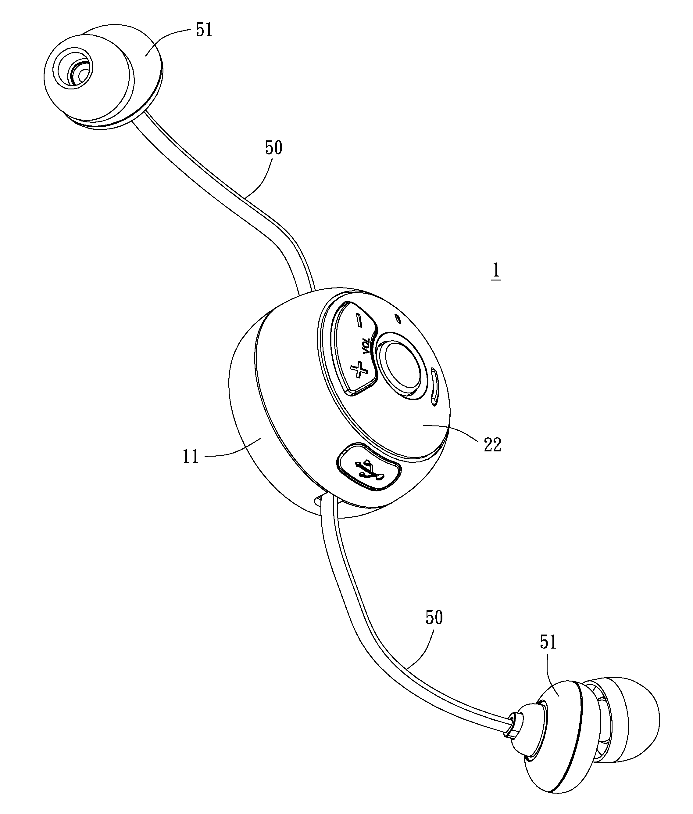
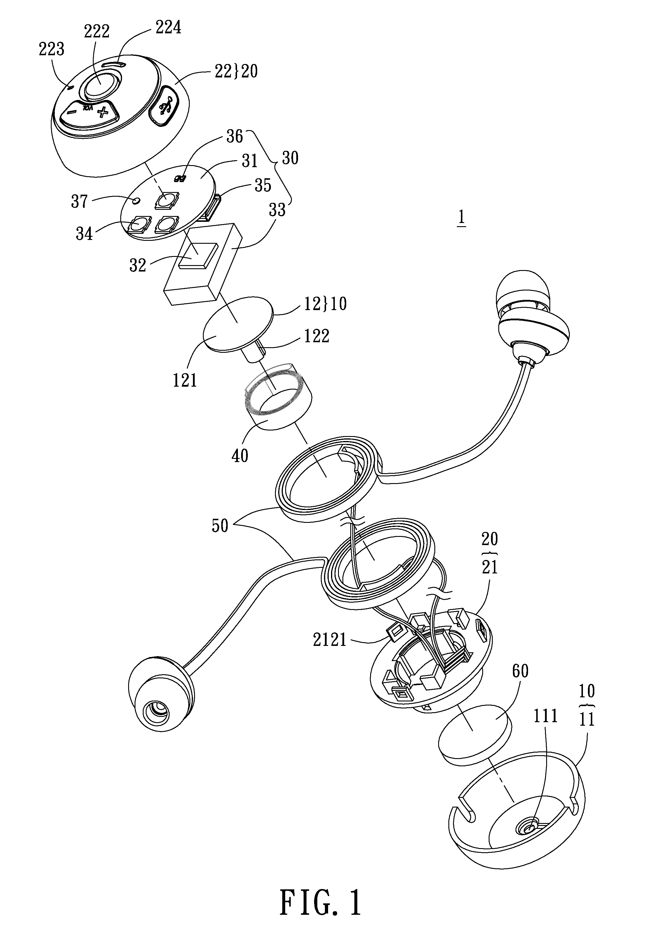
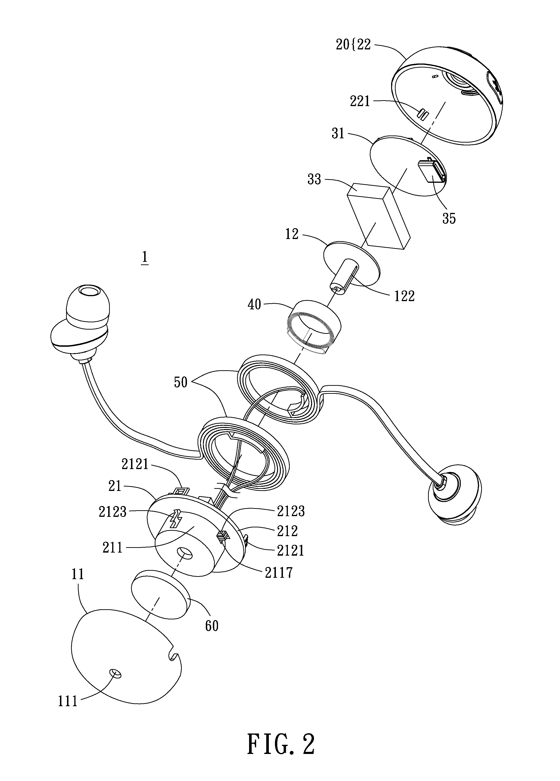
[0020]FIG. 1 is a schematic exploded diagram of a wireless earphone 1 of the present disclosure. The present disclosure provides a wireless earphone 1, which has a fixing module 10, a rotating case 20, an electronic module 30 disposed on the rotating case 20, a tape spring 40, an earphone cable 50 wound around the rotating case 20, and a fastening module 60 disposed between the fixing module 10 and the rotating case 20. One end of the tape spring 40 is attached to the fixing module 10, and the other end is attached to the rotating case 20.
[0021]As shown in FIG. 1, the fixing module 10 includes a lower cover 11 and a fixing element 12. The outer surface of the lower cover 11 can have a clip (not shown in the figure), to be clipped on clothes, bags and such when the user is walking or exercising, so that the user does not have to employ a hand to hold the wireless earphone 1. In the present embodiment, the fixing element 12 is a fixing column 12, which has an engagement groove 122 (refer to FIG. 2). The lower cover 11 is bowl-shaped, and has a fixing aperture 111 at its center position. The fixing aperture 111 roughly has the same diameter as the fixing column 12 does, such that an end of the fixing column 12 is disposed in the fixing aperture 111. The fixing column 12 can be fixed to the fixing aperture 111 by screws, engagement, or other methods not limited herein. In the present embodiment as shown in FIG. 2, the fixing module 10 further has a round plate 121 positioned at the other end of the fixing column 12, also the opposite end of the lower cover 11.
[0022]As shown in FIG. 2, the rotating case 20 has a rotating base 21 and an upper cover 22. The upper cover 22 is fixed to the rotating base 21. As shown in FIG. 2 and FIG. 3, the rotating base 21 has a cup portion 211 and an annular plate 212. The annular plate 212 is extended from the top edge of the cup portion 211. As shown in FIG. 3 and FIG. 4, multiple first latches 2121 are evenly spaced on the annular plate 212. As shown in FIG. 5, the inner edge of the annular plate 212 (also the top end of the cup portion 211) has a diameter roughly equal to that of the round plate 121, such that the round plate 121 can be disposed on top of the cup portion 211, to protect and keep out the dust from the module inside the cup portion 211. Furthermore, multiple battery bases 2122 and a cable aperture 2123 are disposed on the annular plate 212 (shown in FIG. 2).
[0023]As shown in FIG. 2 and FIG. 3, multiple second latches 221 are disposed on the upper cover 22 corresponding to the first latches 2121. The first latches 2121 and the second latches 221 are male and female latches for engaging with each other. In the present embodiment, the first latches 2121 are frame-shaped, and the second latches 221 are protruding-shaped. The protruding structures engage with the frame-shaped structures, such that the upper cover 22 and the rotating base 21 can be fixed by the engagement of the first latches 2121 with the second latches 221. As shown in FIG. 1, multiple keys 222, a sound receiving aperture 223, and a light passing aperture 224 are disposed on the upper cover 22. The keys 222 can control the volume, select songs, turn the device on and off, etc. A transparent glass (not shown in the figure) can be disposed at the light passing aperture 224. The upper cover 22 can have a display board (not shown in the figure) to display information on the song being played.
[0024]As shown in FIG. 3 and FIG. 4, the cup portion 211 has a lateral wall 2111 and a bottom face 2112. Multiple openings 2113 and a cable aperture 2117 are disposed on the lateral wall 2111. Three protruding pieces 2114, two fixing units 2115, and an engagement piece 2116 are disposed at the bottom face 2112. A round aperture 2118 is disposed at the center of the bottom face 2112. The fixing column 12 can pass through the round aperture 2118, such that the cup portion 211 can be disposed inside the lower cover 11, and the rotating case 20 can rotate about the fixing column 12. The protruding pieces 2114 and the lateral face wall 2111 have a fixed gap between them. The fixing units 2115 are engaged between multiple protruding pieces 2114. One end of each of the fixing units 2115 abuts the lateral wall 2111. The engagement piece 2116 and the lateral wall 2111 have a fixed distance between them. The amounts of the protruding piece 2114, the fixing unit 2115 and the engagement piece 2116 are not limited herein.
[0025]As shown in FIG. 1, the electronic module 30 includes a circuit board 31, a transceiver chip 32, a battery 33, a micro switch 34, an electrical connector 35, a lighting unit 36, and a microphone 37. As shown in FIG. 1 and FIG. 5, the battery 33 is disposed on the battery base 2122 of the annular plate 212. The circuit board 31 is electrically connected to the battery 33. The transceiver chip 32 is disposed between the circuit board 31 and the battery 33. The micro switch 34, the lighting unit 36 and the microphone 37 are disposed on the circuit board 31 at the face facing the upper cover 22 such that the key 222 correspond to the micro switch 34 so that when a user presses the key 222 the micro switch 34 is triggered to transmit command signals. The lighting unit 36 corresponds to the light passing aperture 224, for providing lighting to notify the user of the status of the wireless earphone 1. The microphone 37 corresponds to the sound receiving aperture 223, for recording the user's voice. The electrical connector 35 is disposed on the other face of the circuit board 31, able to charge the battery 33 and transmit signals to the wireless earphone 1. This structure can be utilized to make the electronic module 30 rotate along with the rotating case 20. In the present disclosure, the transceiver chip 32 is a Bluetooth chip, and the lighting unit 36 is an LED light.
[0026]As shown in FIG. 3, the tape spring 40 is wound around the fixing column 12, and partially disposed between the engagement piece 2116 and the lateral wall 2111. One end of the tape spring 40 is attached to one side of the engagement piece 2116, and the other end of the tape spring 40 is fixed to the engagement groove 122 of the fixing column 12, such that the tape spring 40 extends or contracts to provide a restoring force to the rotating case 20 as the latter rotates.
[0027]As shown in FIG. 5, the earphone cable 50 can be a left earphone cable or a right earphone cable, respectively wound around the cup portion 211 in a clockwise and counter-clockwise direction. As shown in FIG. 2, FIG. 3 and FIG. 5, one end on each of the left and right earphone cables respectively pass through different openings 2113, such that the earphone cables 50 can be partially accommodated between the protruding piece 2114 and the lateral wall 2111, and be fixed to the fixing unit 2115. Multiple cables extend from the earphone cables 50. In the above mentioned state of the cables, the earphone cables 50 pass through the cable aperture 2117 of the lateral wall 2111 and the cable aperture 2123 on the annular plate 212, extend toward the upper cover 22 and connect to the circuit board 31. As shown in FIG. 6, the other end of cables 50 pass through the lower cover 11 and have a speaker part 51. The speaker part 51 can also be replaced by a microphone (not shown in the figures). This structural configuration allows both the left and right earphone cables to simultaneously be extended or contracted, and drives the cup portion 211 to rotate about the fixing column 12 when extending, further rotating the rotating case 20 and the electronic module 30. Furthermore, when the earphone cables 50 do not have precise lengths, the method of passing the above mentioned earphone cables 50 through the cable apertures 2117 and 2123 provides a storage solution for neatly storing extra lengths of the earphone cables 50, especially relative to the method of connecting the earphone cables 50 directly to the circuit board 31.
[0028]As shown in FIG. 1, the fixing module 60, which can be the ratchet, combination of toggle piece with track, or steel ball mentioned in the description of related art, is disposed between the rotating base 21 and the lower cover.
[0029]As shown in FIG. 3, as mentioned above, when the user pulls on the earphone cable 50, the rotating case 20 rotates about the fixing column 12 and extends or contracts the tape spring 40, therefore the tape spring 40 will apply a restoring force. Even when the user is no longer applying force on the earphone cables, the rotating case 20 is subject to the restoring force of the tape spring 40, and rotates back to its original position relative to the fixing module 10, such that the earphone cable 50 does not expose a certain length outside the lower cover 11. The fastening module 60 fixes the rotating case 20 to a determined position relative to the fixing module 10, such that the user can decide how much of the earphone cables 50 are exposed outside the lower cover 11. Moreover, when the earphone cables 50 are pulled to the end, the restoring force of the tape spring 40 rotates the rotating case 20 back to its original position, retracts the earphone cables 50 such that most of the earphone cables 50 are wound around the cup portion 211 and not exposed outside the lower cover 11, thereby preventing the earphone cables 50 from tangling or being damaged due to tugging.
[0030]In summary of the above, the present disclosure has the following special features:
[0031]1. By disposing the electronic module on the battery base of the rotating case, the electronic module is moved in conjunction when the earphone cables are pulled to drive the rotating case, avoiding tugging of the cables.
[0032]2. By passing the earphone cables through the cable apertures of the annular plate and the lateral wall, a storage solution for neatly storing extra lengths of the earphone cables is provided, reducing the need for precise lengths.
[0033]The descriptions illustrated supra set forth simply the preferred embodiments of the present disclosure; however, the characteristics of the present disclosure are by no means restricted thereto. All changes, alternations, or modifications conveniently considered by those skilled in the art are deemed to be encompassed within the scope of the present disclosure delineated by the following claims.

PUM

no PUM

Description & Claims & Application Information

We can also present the details of the Description, Claims and Application information to help users get a comprehensive understanding of the technical details of the patent, such as background art, summary of invention, brief description of drawings, description of embodiments, and other original content. On the other hand, users can also determine the specific scope of protection of the technology through the list of claims; as well as understand the changes in the life cycle of the technology with the presentation of the patent timeline. Login to view more.
Why Eureka
Try Eureka