

Dental trap
a technology of dental traps and traps, applied in the field of dental traps, can solve problems such as patient discomfort and patient difficulty in swiping
- Summary
- Abstract
- Description
- Claims
- Application Information
AI Technical Summary
Benefits of technology
Problems solved by technology
Method used
Image

Examples
Embodiment Construction
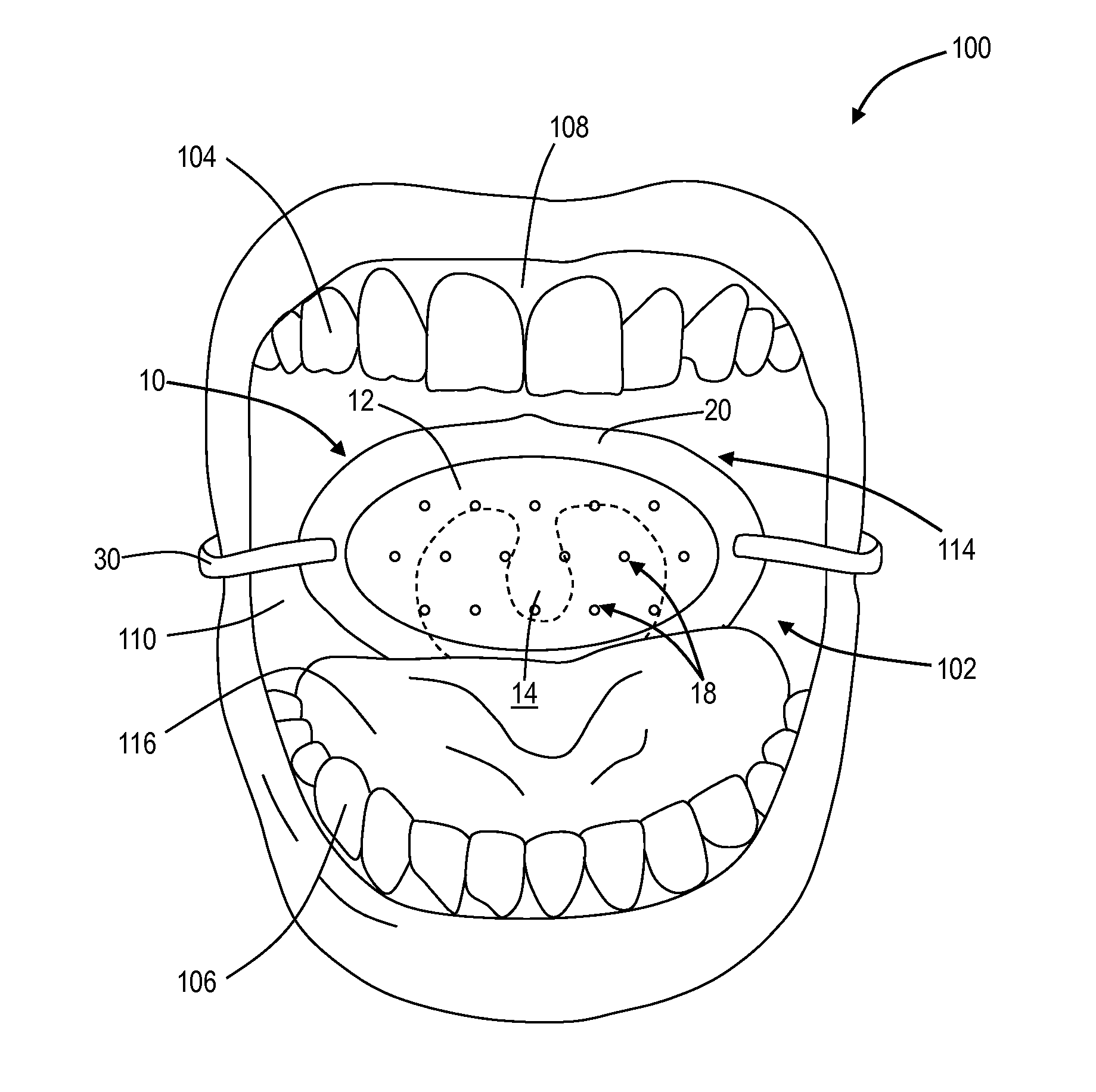
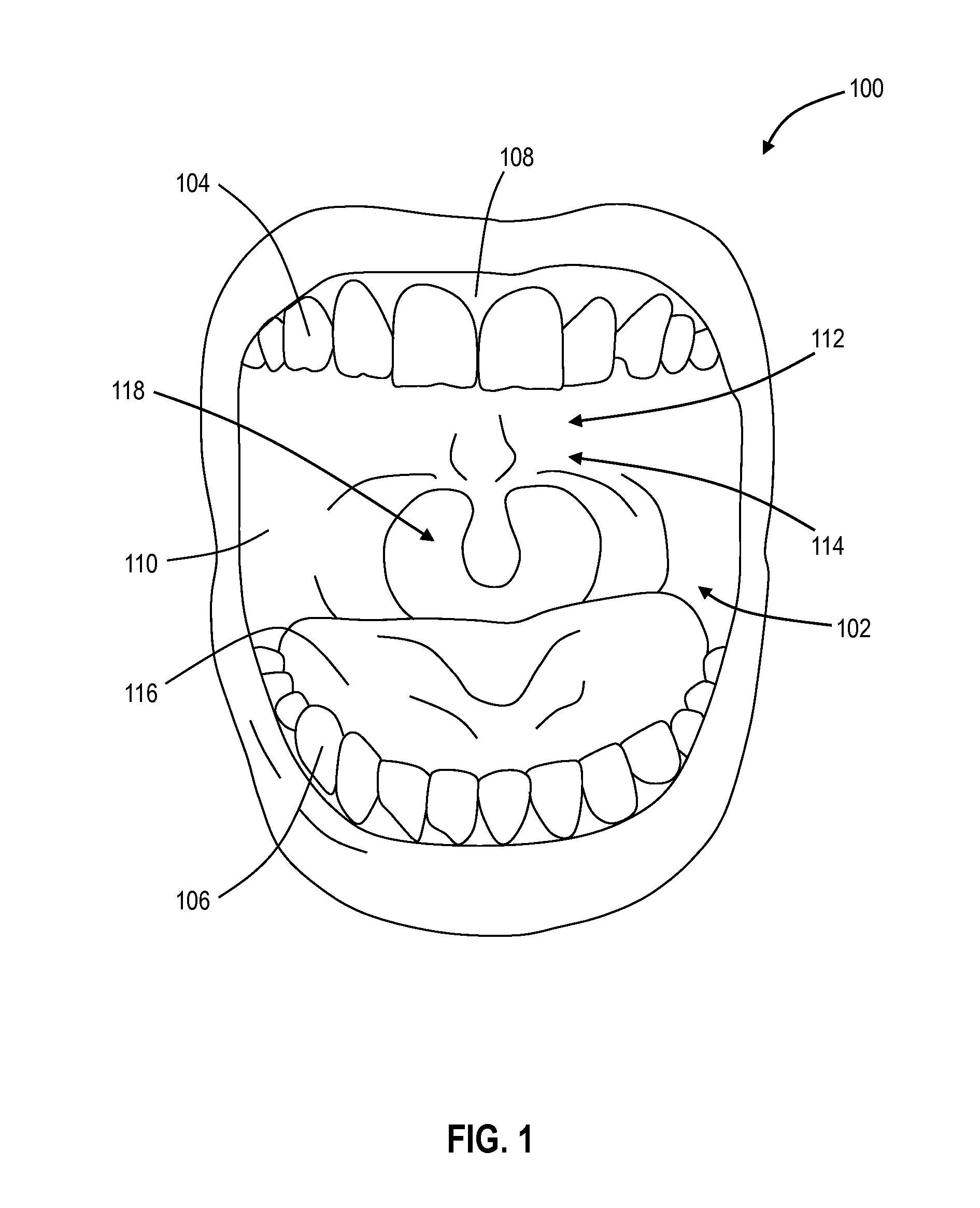
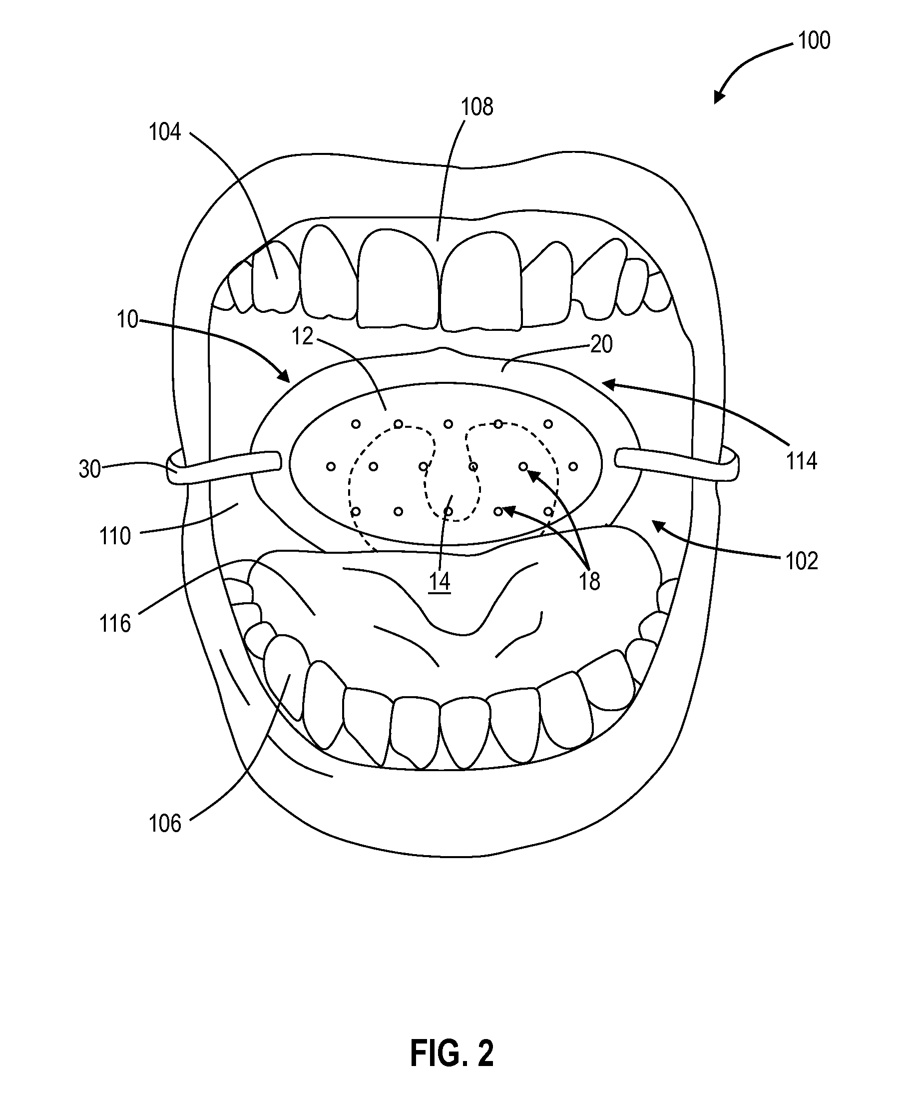
[0015]A mouth cavity 102 of a patient 100 is shown in FIG. 1. Mouth cavity 102 of patient 100 is bounded anteriorly (i.e., in front) and laterally (i.e., side-to-side) by teeth, specifically by a row of upper teeth 104 attached to the maxilla or upper jaw (not shown) of patient 100 and a row of lower teeth 106 attached to the mandible or lower jaw (not shown) of patient 100, and also by gums 108 and cheeks 110 of patient 100. Mouth cavity 102 of patient 100 is bounded superiorly (i.e., on top) by a hard palate region 112 and a soft palate region 114 located posteriorly of (i.e., behind) the hard palate region 112. Soft palate region 114 may also be referred to as the velum or the muscular palate. Mouth cavity 102 of patient 100 is bounded inferiorly (i.e., on bottom) by a tongue 116 primarily.
[0016]Mouth cavity 102 of patient 100 is open posteriorly (i.e., in back) to a throat 118. Throat 118 includes the pharynx (not shown) which communicates with both the esophagus (not shown) for...
PUM
 Abstract
Description
Claims
Application Information