
Flight deck display systems and methods for generating in-trail procedure windows including aircraft flight path symbology

a flight deck and display system technology, applied in the field of flight deck display systems, can solve the problems of limited itp windows generated by flight deck display systems in certain aspects, and do not provide pilots with readily comprehendible ways

Inactive Publication Date: 2014-07-31
HONEYWELL INT INC
View PDF3 Cites 42 Cited by
  • Summary
  • Abstract
  • Description
  • Claims
  • Application Information

AI Technical Summary

Benefits of technology

The patent describes a flight deck display system that can be used on an airplane to show information about the current position of the airplane and an intruder aircraft that may be nearby. The system includes a display, a wireless communication module, and a controller that generates a vertical window on the display with graphics and information about the airplanes. The controller can also receive data about the current flight path of the intruder aircraft and update the display with the information about the flight path. The technical effect of this system is to improve the safety and situational awareness of pilots in airplanes, allowing them to better avoid collisions and maintain safe flying habits.

Problems solved by technology

However, ITP windows generated by flight deck display systems remain limited in certain aspects.
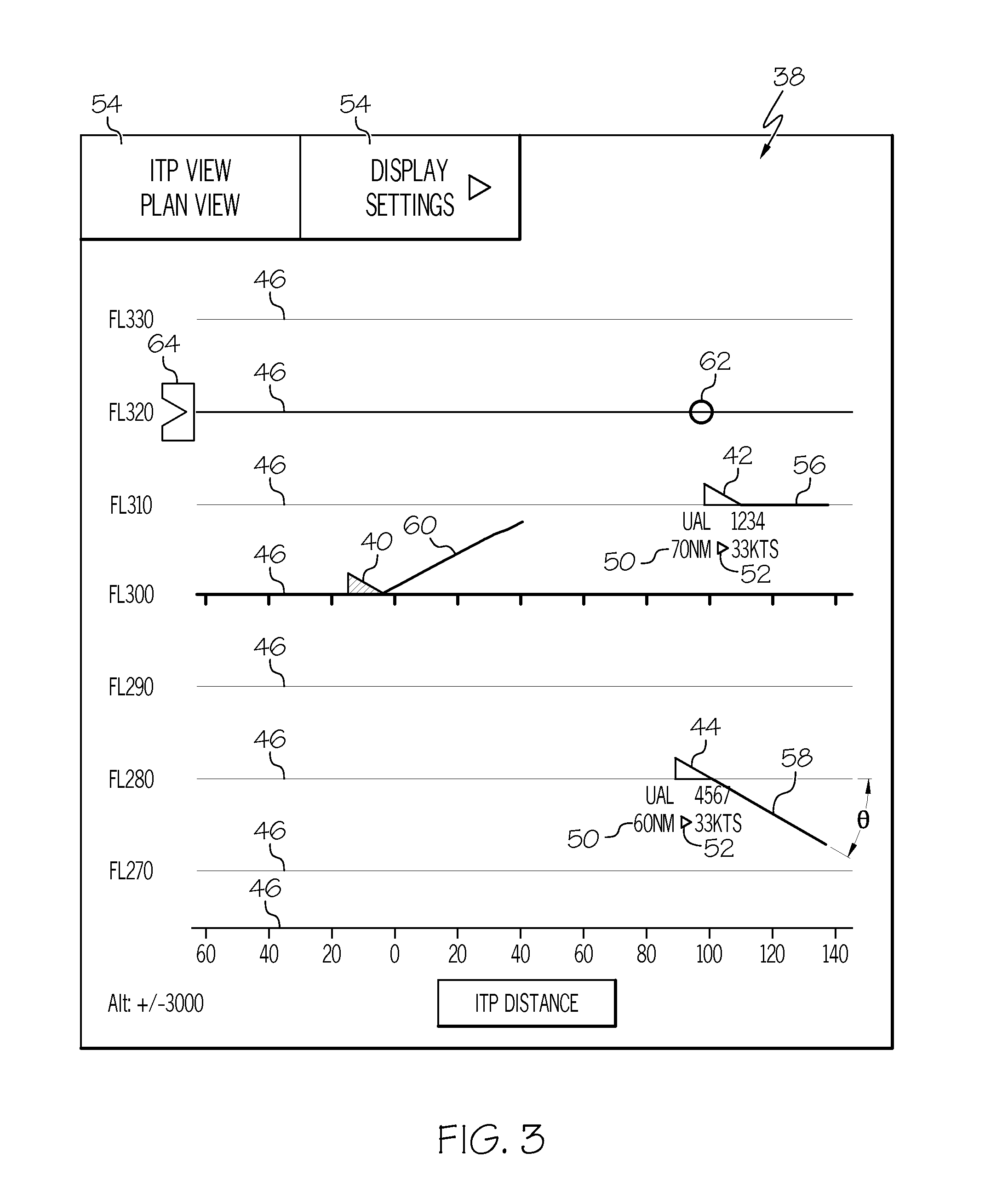
For example, and without implication that any such limitations have been recognized in the prior art, conventionally-generated ITP windows generally do not provide a pilot with readily comprehendible manner in which to predict future transitions in flight level by intruder aircraft and thereby determine in advance whether a transition to a soon-to-be-vacated flight level might be warranted.

Method used


Image

  • Flight deck display systems and methods for generating in-trail procedure windows including aircraft flight path symbology
  • Flight deck display systems and methods for generating in-trail procedure windows including aircraft flight path symbology
  • Flight deck display systems and methods for generating in-trail procedure windows including aircraft flight path symbology

Examples


Embodiment Construction

[0012]The following Detailed Description is merely exemplary in nature and is not intended to limit the invention or the application and uses of the invention. Furthermore, there is no intention to be bound by any theory presented in the preceding Background or the following Detailed Description. Terms such as “comprise,”“include,”“have,” and variations thereof are utilized herein to denote non-exclusive inclusions. Such terms may thus be utilized in describing processes, articles, apparatuses, and the like that include one or more named steps or elements, but may further include additional unnamed steps or elements.

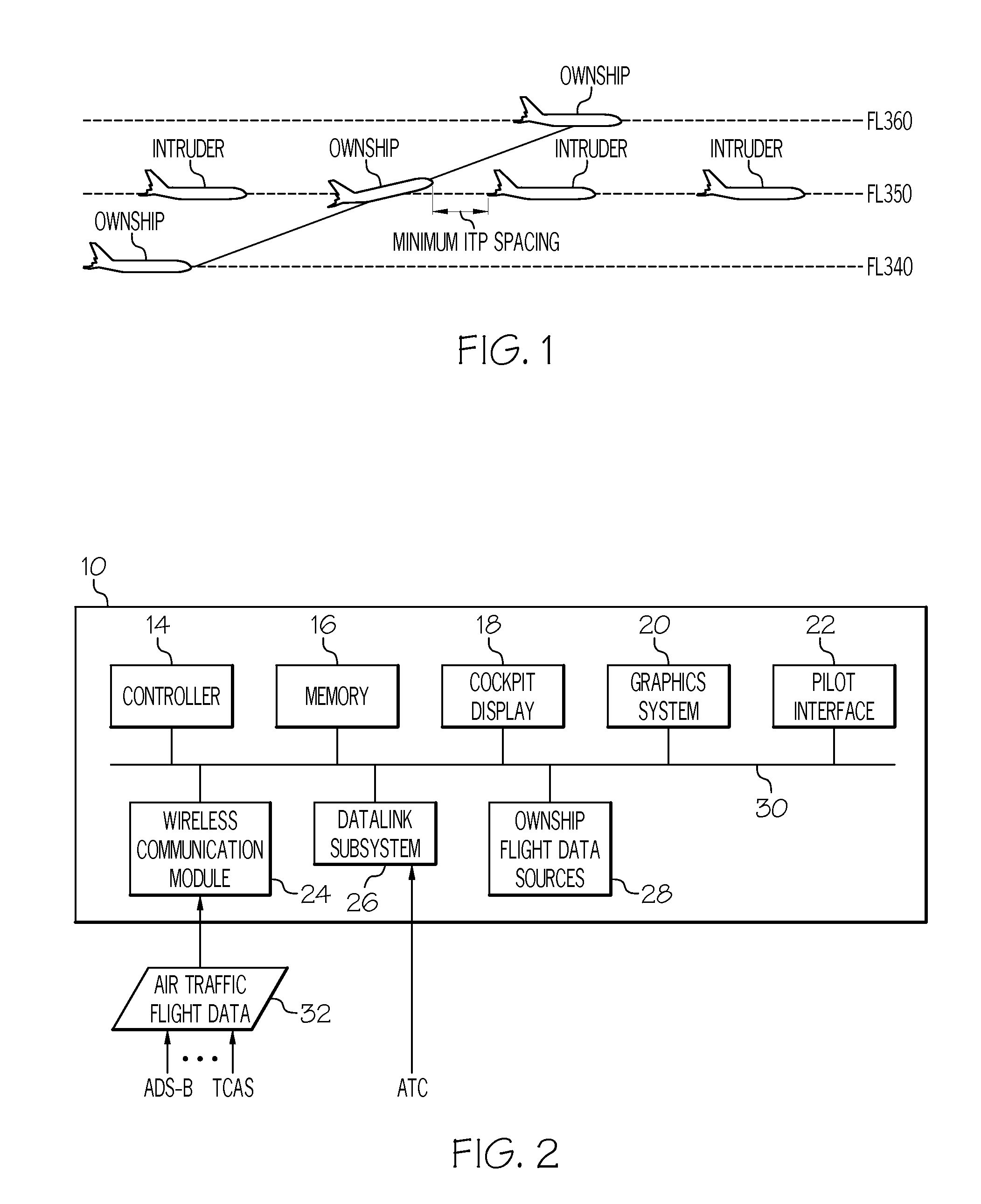
[0013]The term “pilot,” as appearing herein, encompasses all members of a flight crew. The terms “host aircraft” or “ownship aircraft” are utilized to refer to an aircraft on which the below-described flight deck display system is deployed. The host aircraft can also be described as the “ITP aircraft” when in the process of requesting and performing an ITP maneuver. Neig...


PUM


Abstract

Embodiments of a flight deck display system for deployment onboard a host aircraft are provided, as are embodiments of a method carried-out by a flight deck display system. In one embodiment, the flight deck display system includes a cockpit display, a wireless communication module, and a controller operatively coupled to the cockpit display and to the wireless communication module. The controller is configured to generate a vertical In-Trail Procedure (ITP) window on the cockpit display, which includes graphics representative of the current position of the host aircraft, the current position of an intruder aircraft when present within a predetermined distance of the host aircraft, and a plurality of flight levels. The controller is further configured to receive data from which the current flight path of the intruder aircraft can be derived; and periodically update the vertical ITP window to include flight path symbology indicative of the current flight path of the intruder aircraft.

Description

TECHNICAL FIELD[0001]The following disclosure relates generally to flight deck display systems and, more particularly, to embodiments of systems and methods for generating In-Trail Procedure windows including, for example, symbology representative of the flight path of the host aircraft and / or one or more intruder aircraft.BACKGROUND[0002]The flight level at which an aircraft flies can affect fuel consumption, emission rates, and other measures of aircraft performance. It is thus desirable to enable aircraft to frequently and freely transition flight levels as conditions, such as wind conditions and turbulence levels, vary at different flight levels. When an aircraft transitioning flight levels does so in the presence of nearby aircraft occupying an intervening flight level, the transition in flight level is commonly referred to as an “In-Trail Procedure” or, more simply, an “ITP.” ITP protocols have been established to ensure safe and efficient transition in flight levels in the pr...

Claims


Application Information

Patent Timeline
Patent Type & Authority Applications(United States)
IPC IPC(8): G08G5/00
CPCG08G5/0008G08G5/0021G08G5/0078
Inventor SAMUTHIRAPANDIAN, SUBASHA, FAZURUDHEENJOHNSON, MARKUS
Owner HONEYWELL INT INC
Learn More