Unlock instant, AI-driven research and patent intelligence for your innovation.

Cooling for a fluid flow machine

a fluid flow machine and cooling technology, applied in the field of turbines, can solve the problems of increasing the demands on the materials to be used, affecting the operation of the engine, so as to improve the heat exchange with the surrounding environment, the surface area of the piston-equalizing line is enlarged, and the effect of reducing the number of parts

Inactive Publication Date: 2014-07-31
SIEMENS AG
View PDF30 Cites 29 Cited by
  • Summary
  • Abstract
  • Description
  • Claims
  • Application Information

AI Technical Summary

Benefits of technology

The invention is about improving the heat exchange between steam and the surroundings in a piston-equalizing line. This is achieved by enlarging the surface area of the piston-equalizing line and arranging inner and outer cooling ribs on it. The cooling ribs improve the thermal interaction between the steam and the piston-equalizing line, resulting in a more uniform temperature. The design is simple and cost-effective. Overall, the invention allows for better thermal equalization in the piston-equalizing line and reduces the likelihood of fouling.

Problems solved by technology

Modern steam turbines have steam temperatures of over 600° C. Such high temperatures place increased demands on the materials to be used.
However, this entails that the hot steam from the second flow region is guided in part over the thrust-equalizing piston and thus impinges on the outer housing.
The outer housing is thus subject to high thermal loading at this point.
It would not be possible to use a standard material for the outer housing at this point.
Therefore, more expensive materials, for example GGGSIMO, would have to be used at this point.
Such materials are generally comparatively expensive and, moreover, are not easily cast, leading to material defects.

Method used


Image

  • Cooling for a fluid flow machine
  • Cooling for a fluid flow machine
  • Cooling for a fluid flow machine

Examples


Embodiment Construction

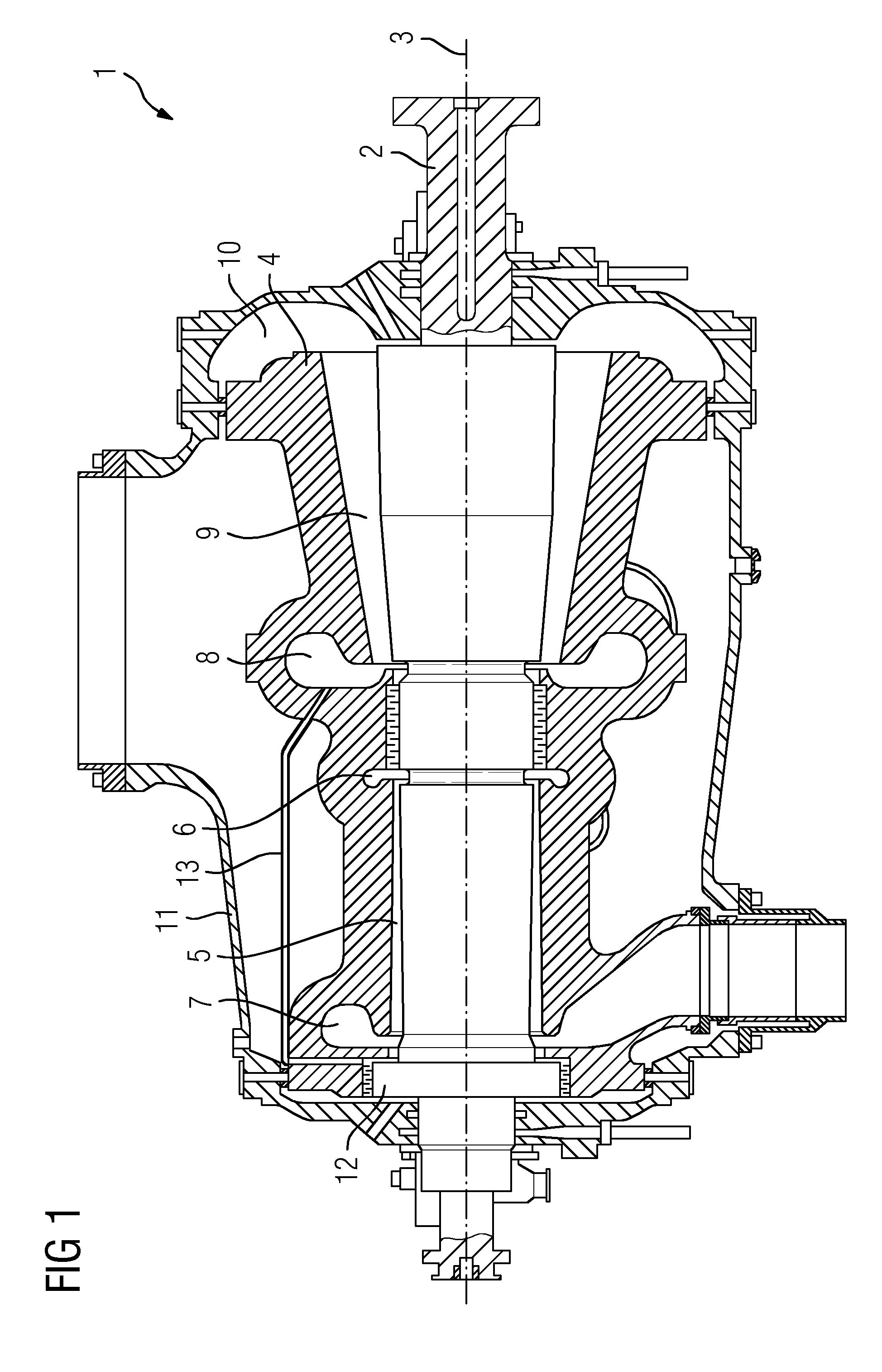
[0017]FIG. 1 shows a steam turbine1 as an embodiment of a turbomachine. The steam turbine 1 comprises, substantially, a rotor 2 rotatably mounted about an axis of rotation 3. An inner housing 4 is arranged about the rotor 2, with a first flow duct 5, which can also be designated as the high-pressure flow region, being formed between the inner housing 4 and the rotor 2. The flow direction of the first flow duct 5 is to the left as shown in the representation according to FIG. 1. In operation, steam flows, via a HP fresh steam region 6, through the inner housing 4 into the first flow duct 5. The steam flowing into the first flow duct 5 via the high-pressure fresh steam region 6 cools down in the flow direction, emerges from the steam turbine 1 via a HP outflow region 7 and, after an intermediate superheater stage, is reintroduced, via an IP inflow region 8 into the steam turbine, to a second flow duct 9. Finally, the steam flows out of the steam turbine 1 via the intermediate-pressure...


PUM


Abstract

A fluid flow machine, in particular a steam turbine, is provided having a piston-equalizing line which conducts a vapour from a fresh vapour region of a second flow duct to a thrust-equalizing piston, wherein the surface of the piston-equalizing line is enlarged, and wherein the inner surface of the piston-equalizing line is enlarged.

Description

CROSS REFERENCE TO RELATED APPLICATIONS[0001]This application is the US National Stage of International Application No. PCT / EP2012 / 065103 filed Aug. 2, 2012, and claims the benefit thereof. The International Application claims the benefit of European Application No. EP11179311 filed Aug. 30, 2011. All of the applications are incorporated by reference herein in their entirety.FIELD OF INVENTION[0002]The invention relates to a turbomachine comprising a rotor mounted rotatably about an axis of rotation, an inner housing arranged about the rotor and an outer housing arranged about the inner housing, wherein a first flow region and a second flow region, formed in the opposite flow direction to the first flow region, are arranged between the rotor and the inner housing, wherein the rotor has a thrust-equalizing piston, wherein a piston-equalizing line is formed for introducing steam between the inner housing and the thrust-equalizing piston.BACKGROUND OF INVENTION[0003]In turbomachines, s...

Claims


Application Information

Patent Timeline
Patent Type & Authority Applications(United States)
IPC IPC(8): F01D3/04
CPCF01D3/04F05D2260/2322F01D3/02F01D25/26F02C7/141F05D2220/31F05D2260/213F05D2260/22141F05D2260/2214
Inventor KASTNER, CHRISTOPHPOTTER, RUDOLF
Owner SIEMENS AG