Eureka AIR delivers breakthrough ideas for toughest innovation challenges, trusted by R&D personnel around the world.

Bone support apparatus

a technology of bone support and support rod, which is applied in the field of surgical implantable devices, can solve the problems of inability to flex or absorb shock and movement of the patient's trunk or spine, the amount of expansion available, and the rigidity of materials

Active Publication Date: 2014-08-07
DEPUY SYNTHES PROD INC
View PDF4 Cites 23 Cited by
  • Summary
  • Abstract
  • Description
  • Claims
  • Application Information

AI Technical Summary

Benefits of technology

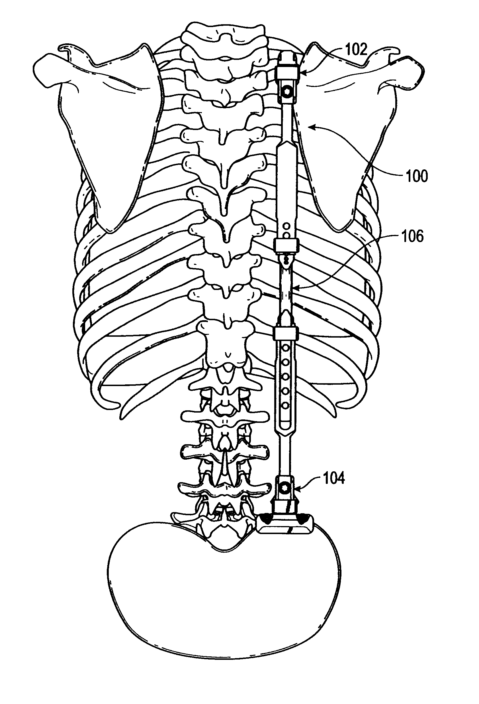
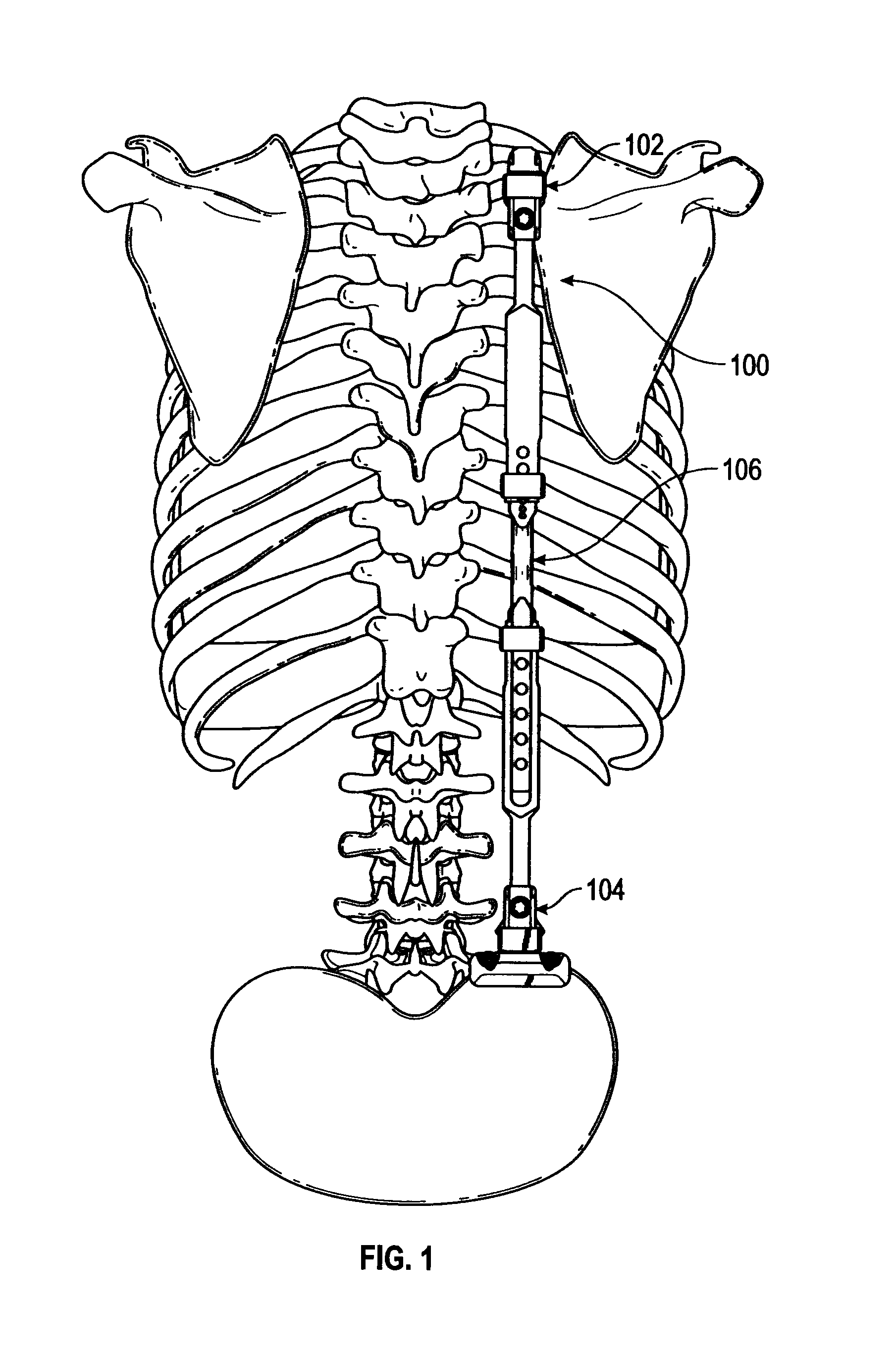
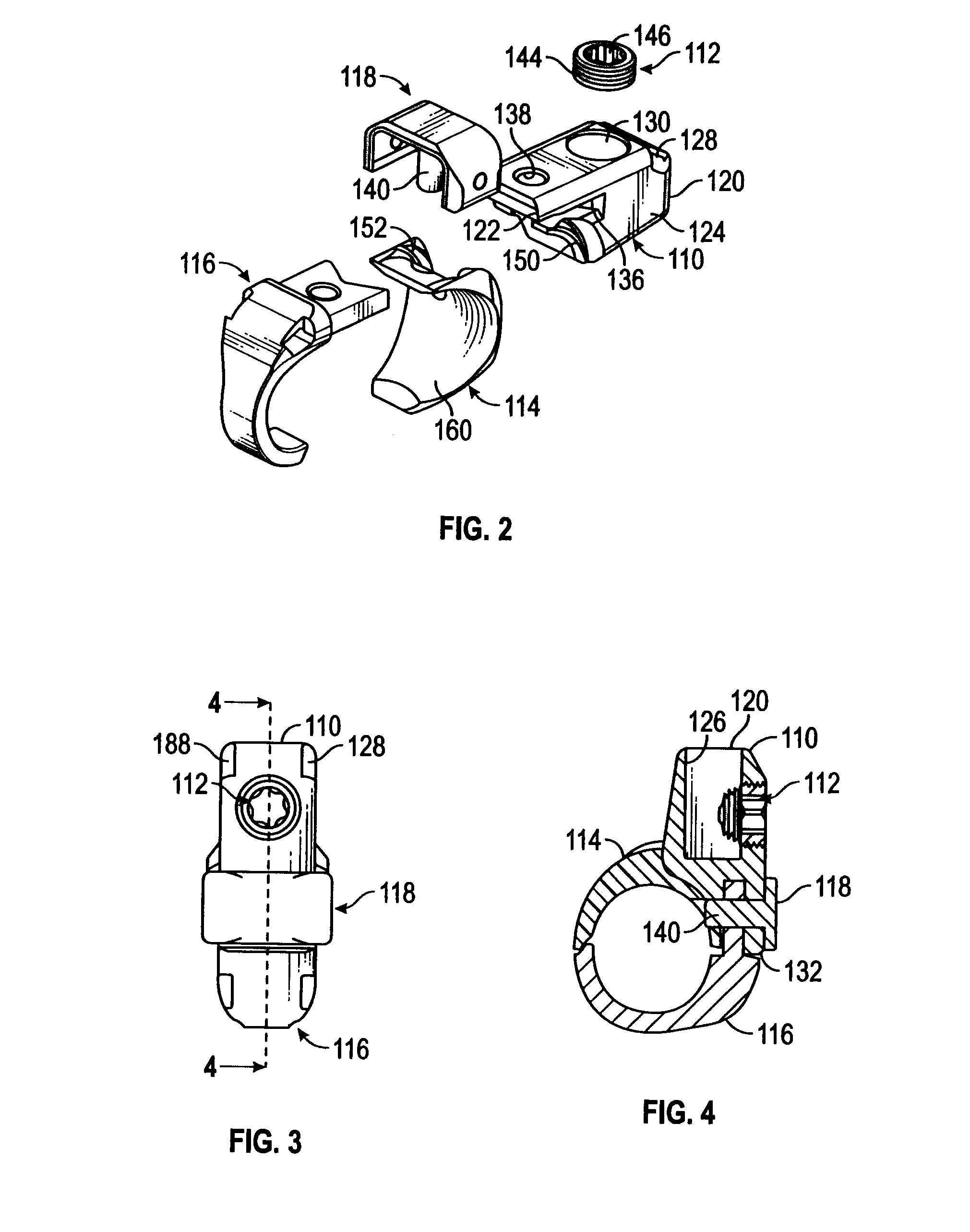
The patent describes a bone support apparatus and kit that includes a first bone connector, a second bone connector, and an adjustable rod assembly that can adjust the distance between the two connectors. This allows for a flexible and customizable support system for patients' bones. The technical effects include improved patient outcomes, reduced complications, and more efficient treatment for bone-related injuries and ailments.

Problems solved by technology

Available expandable sections have a kyphosis radius, which may tend to push the patient's upper thoracic forward and may inadvertently contribute to increased kyphosis in some patients.
Further, since the expandable sections of available EPR devices are typically limited to the thoracic region, the amount of expansion available is limited compared to the length of the total implantable EPR device, before major surgical revisions (e.g., implanting a larger EPR device) are needed as the patient's body grows.
Available EPR devices are also typically made of rigid materials, and do not allow for flexing or absorbing shocks and movements of the patient's trunk or spine during normal activities carried out by the patient.

Method used


Image

  • Bone support apparatus
  • Bone support apparatus
  • Bone support apparatus

Examples


Embodiment Construction

[0047]Before explaining at least one embodiment of the inventive concepts disclosed herein in detail, it is to be understood that the inventive concepts are not limited in their application to the details of construction and the arrangement of the components or steps or methodologies set forth in the following description or illustrated in the drawings. The inventive concepts disclosed herein are capable of other embodiments or of being practiced or carried out in various ways. Also, it is to be understood that the phraseology and terminology employed herein is for the purpose of description only and should not be regarded as limiting the inventive concepts disclosed and claimed herein in any way.

[0048]In the following detailed description of embodiments of the inventive concepts, numerous specific details are set forth in order to provide a more thorough understanding of the inventive concepts. However, it will be apparent to one of ordinary skill in the art that the inventive conc...


PUM


Abstract

A bone support apparatus includes a first bone connector with a first bone cradle insert configured to contact a patient's bone and constructed of a resilient material, a second bone connector configured to contact a patient's bone, and an adjustable rod assembly having a first end connected to the first bone connector and a second end connected to the second bone connector. The adjustable rod assembly has a first elongated member, a second elongated member, and an expansion member with a first end adjustably connected to the first elongated member and a second end adjustably connected to the second elongated member. The distance between the first bone connector and the second bone connector is adjustable by moving at least one of the first end and the second end relative to the first and second elongated member.

Description

BACKGROUND[0001]1. Field of the Inventive Concepts[0002]The inventive concepts disclosed herein generally relate to surgically implantable devices, and more particularly, but not by way of limitation, to a bone support apparatus and to methods of using same.[0003]2. Brief Description of Related Art[0004]Expandable prosthetic rib (EPR) devices are designed to mechanically stabilize the thorax of a patient to correct three-dimensional thoracic deformities, and to provide improvements in volume for respirations and lung growth in infantile and juvenile patients diagnosed with thoracic insufficiency syndrome. Once the initial implantation procedure is complete and an EPR device is implanted into a patient's body, the EPR device may allow for some adjustability, such as expansion, anatomic distraction, and replacement of some components of the EPR device through subsequent surgical procedures, which are generally less invasive than the initial implantation procedure. Available EPR device...

Claims


Application Information

Patent Timeline
IPC IPC(8): A61B17/70
CPCA61B17/7049A61B17/7014A61B17/7004A61B17/7031A61B17/705A61B17/707A61B17/8695
Inventor RATHBUN, DAVIDKHATCHADOURIAN, ROBERTOJACOBS, SCOTT
Owner DEPUY SYNTHES PROD INC
Why Eureka
Eureka Blog
Learn More