Intervertebral Interference Implants and Instruments

A technology of implants and insertion directions, applied in the field of intervertebral interference implants and instruments, which can solve the problems of patient discomfort and time-consuming

Active Publication Date: 2017-04-12
DEPUY SYNTHES PROD INC +1
View PDF11 Cites 0 Cited by
  • Summary
  • Abstract
  • Description
  • Claims
  • Application Information

AI Technical Summary

Problems solved by technology

Known implants and / or fixation devices can be bulky, causing patient discomfort and requiring time-consuming invasive procedures

Method used


Image

  • Intervertebral Interference Implants and Instruments
  • Intervertebral Interference Implants and Instruments
  • Intervertebral Interference Implants and Instruments

Examples


Embodiment Construction

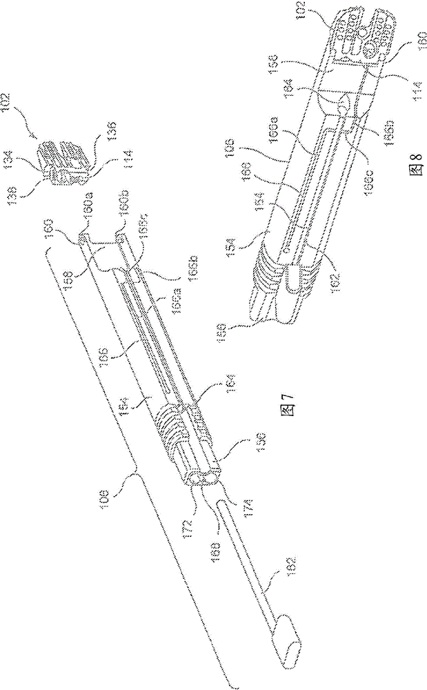
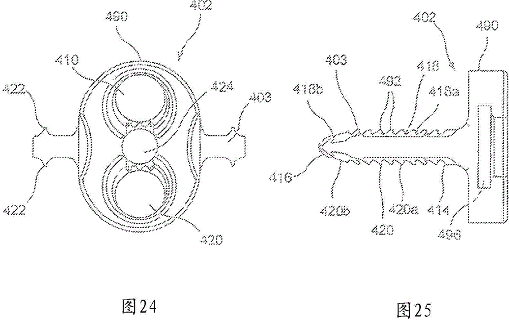
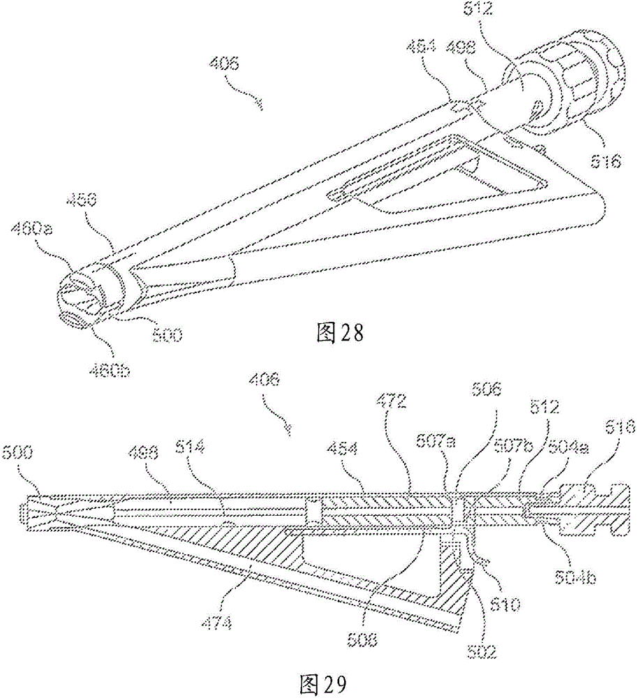
[0128] Combined with the following instructions and attached picture The present invention can be further understood in the appended picture , where similar components are attached by the same picture label mark. The present invention relates to bone therapy devices, and in particular, to minimally invasive posterior fusion devices. Exemplary embodiments of the present invention describe systems and methods for posterior spinal fusion, including implants shaped for insertion into facet joints of adjacent vertebrae along with insertion tools to Facilitates correct insertion and fixation of the implant. Those skilled in the art will appreciate that the systems and methods of the present invention utilize a faster, less invasive technique that requires less muscle stripping and does not require the use of pedicle screws for stabilization. It should be noted that the terms "proximal" and "distal" as used herein are intended to refer to directions toward (proximal) and away fro...


PUM


Abstract

An implant includes an implant body sized and shaped for insertion into a sacro-iliac joint, the implant including a first bone fixation element receiving channel extending through a portion thereof along a first central axis oriented so that, when the implant body is received within the sacro-iliac joint in a desired configuration, a bone fixation element inserted into the first bone fixation element receiving channel will extend into a first one of the bones forming the joint.

Description

[0001] Cross References to Related Applications [0002] This patent application claims priority to US Provisional Patent Application Serial No. 61 / 725,179 filed November 12, 2012, the contents of which are hereby incorporated by reference as if set forth in its entirety herein. Background technique [0003] Posterior spinal fusion can be achieved using, for example, screws, rods, and / or plates to fix two or more adjacent vertebrae relative to each other and to promote fusion. Pedicle screws are used to add extra support to prevent movement of the vertebrae as they fuse. Additionally, it may be desirable to fuse the sacrum and ilium. Known implants and / or fixation devices can be bulky, causing patient discomfort and requiring time-consuming and invasive procedures. Contents of the invention [0004] In one embodiment, an implant may be configured to be inserted into a sacroiliac joint along an insertion direction. The implant may include an implant body having a proximal ...

Claims


Application Information

Patent Timeline
Patent Type & Authority Patents(China)
IPC IPC(8): A61F2/44A61F2/46
CPCA61B17/7055A61F2/30744A61F2/4405A61F2/4455A61F2/447A61F2/4603A61F2/4611A61F2002/3008A61F2002/30266A61F2002/30578A61F2002/30594A61F2002/30774A61F2002/30785A61F2002/30787A61F2002/3082A61F2002/30836A61F2002/30878A61F2002/30879A61F2002/30891A61F2002/30904A61F2002/30995A61F2002/4627A61F2002/4677
Inventor 保罗·巴甫洛夫T.奥维雷斯P.布伦纳
Owner DEPUY SYNTHES PROD INC
Why Eureka
Try Eureka