
Handle device, in particular for hand tools

a technology of hand tools and damping elements, which is applied in the direction of travel carriers, travelling articles, other accessories, etc., can solve the problems of permanent deformation and overextension of the damping unit which comprises a rubber-elastic or elastomeric damping element, and achieves the effect of high overload resistance and cost-effective production

Active Publication Date: 2014-08-14
ROBERT BOSCH GMBH
View PDF81 Cites 8 Cited by
  • Summary
  • Abstract
  • Description
  • Claims
  • Application Information

AI Technical Summary

Benefits of technology

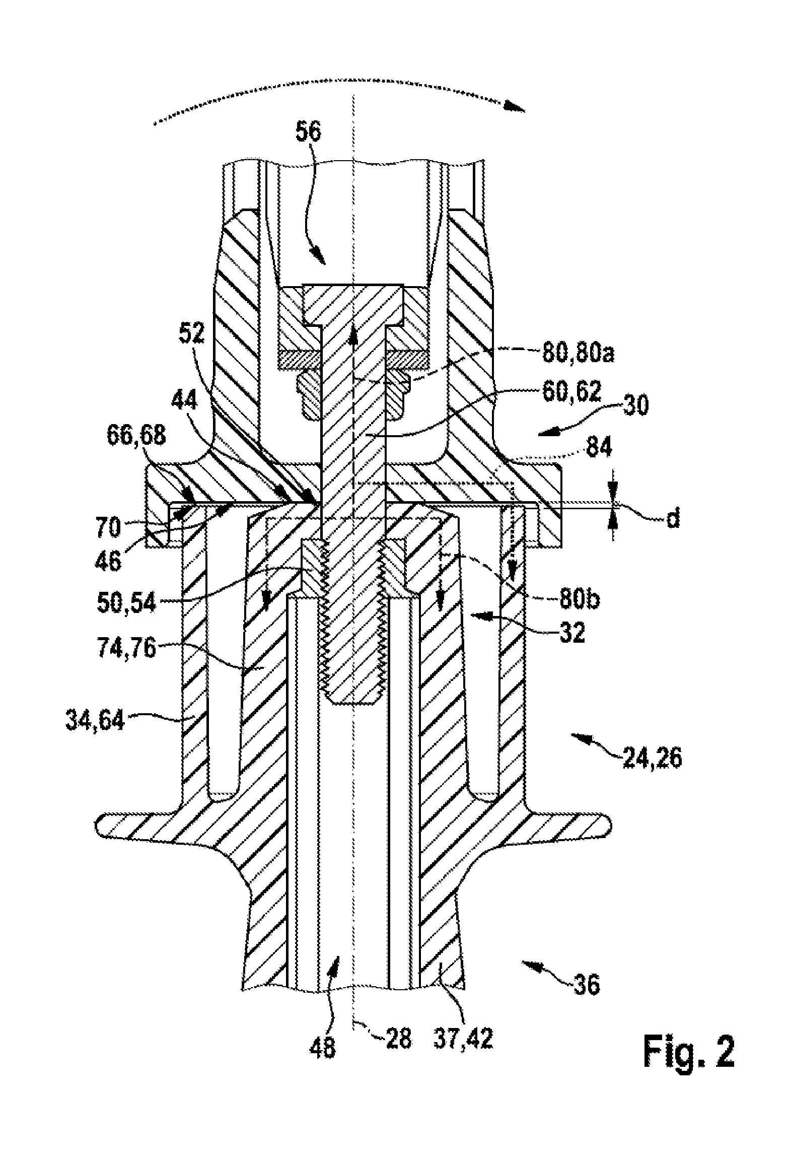
The present invention is about a handle device that has high resistance to overload and is easy and cost-effective to produce. The handle device has an overload protection unit that diverts force flux in case of an overload state, protecting the damping unit from damage. The overload protection device can be compactly arranged in parallel to the force flux path via the damping unit. The handle device has a grip unit with at least one main grip body, making the number of components advantageously reduced. The main grip body is made of plastics material and can be manufactured using thermoplastic or injection-moldable techniques.

Problems solved by technology

Thus, as a result of overloads, for example damping units which comprise a rubber-elastic or elastomeric damping element can be permanently deformed, overextended or, as a result of extreme overstretching, torn.

Method used


Image

  • Handle device, in particular for hand tools
  • Handle device, in particular for hand tools
  • Handle device, in particular for hand tools

Examples


Embodiment Construction

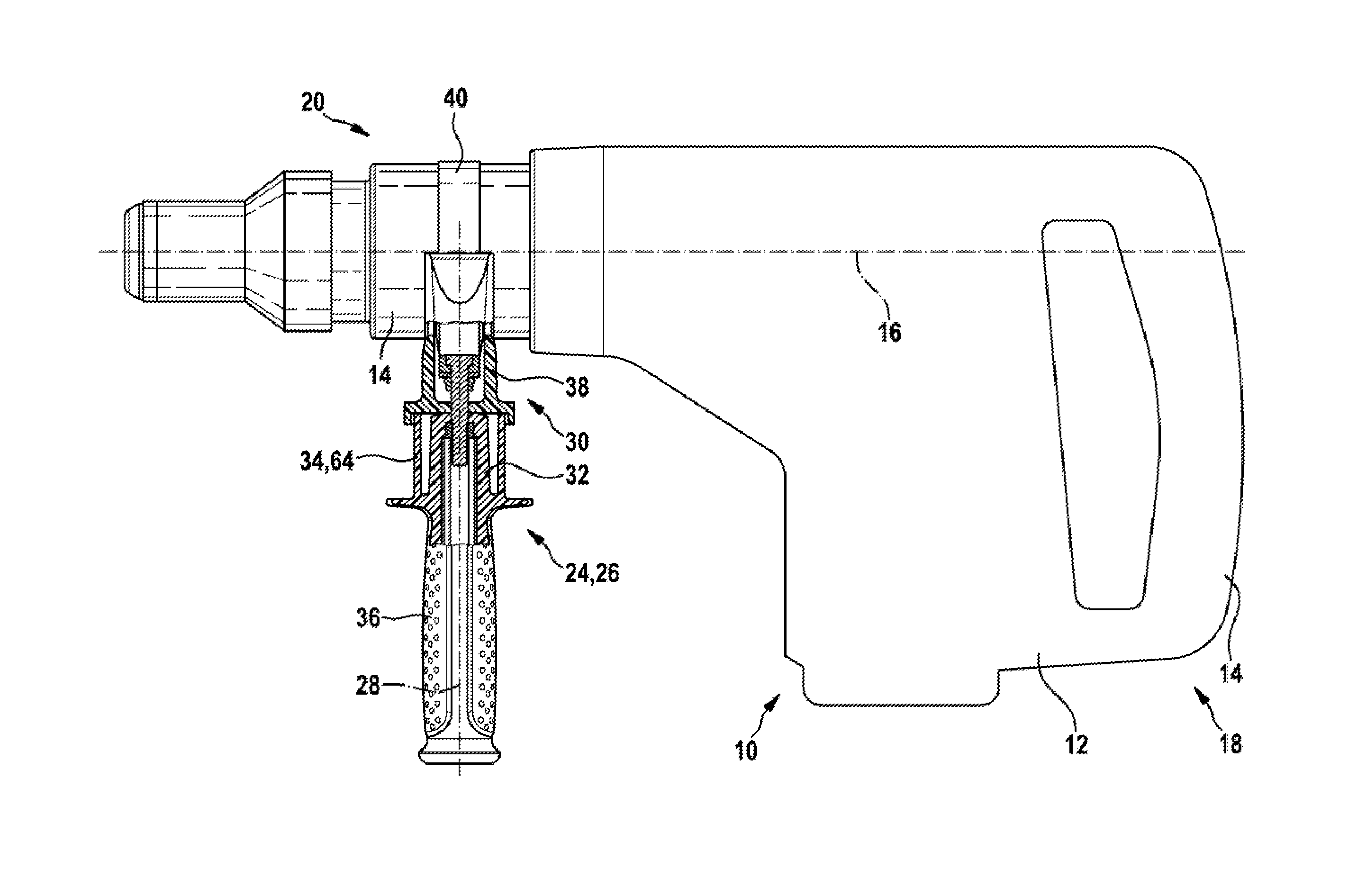
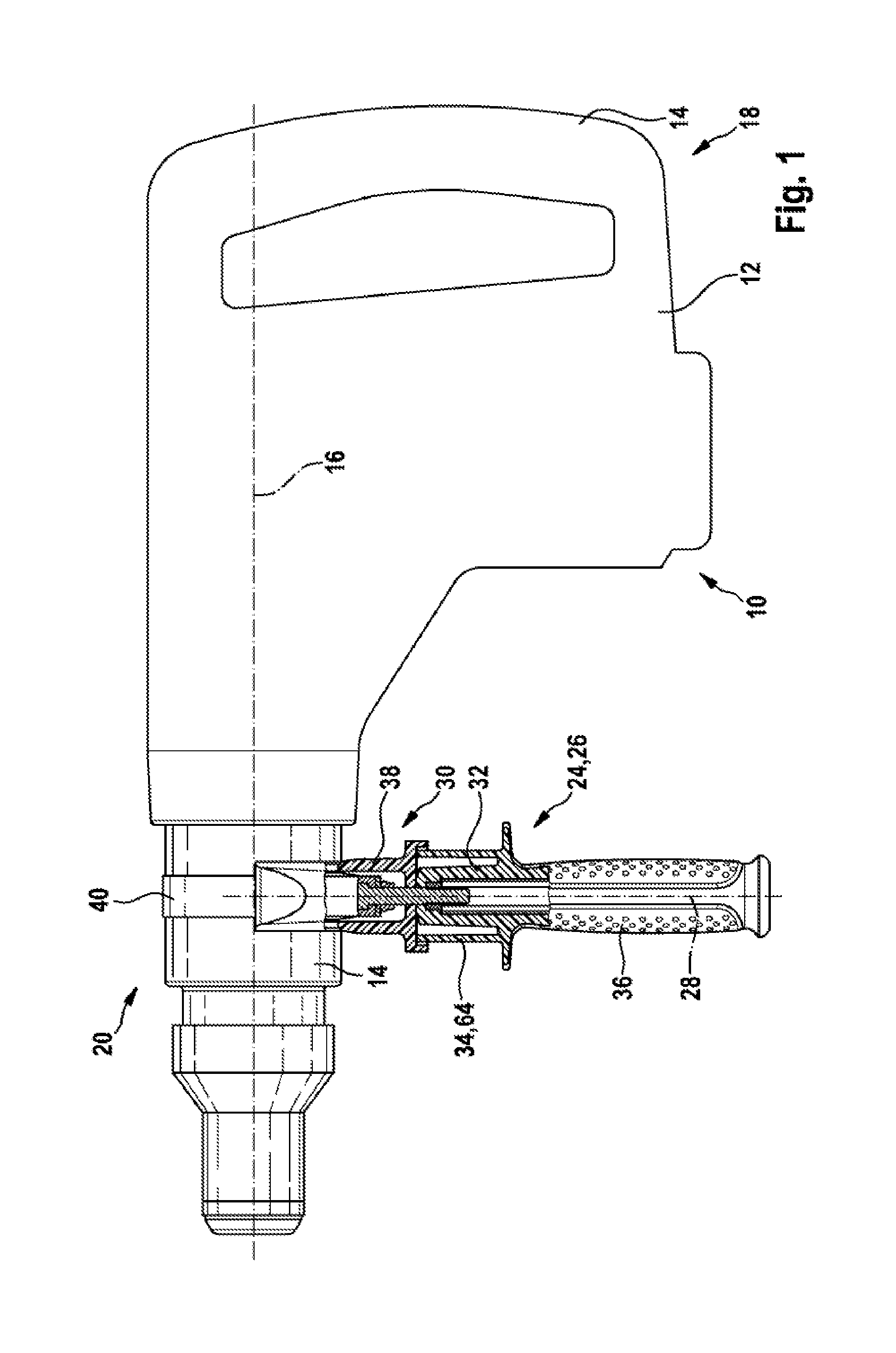
[0033]FIG. 1 shows a hammer drill 10 as an example of a hand tool, in particular a motor-driven hand tool. The hammer drill 10 comprises a housing 12 having a main handle 14 which is integrally formed for example. The main handle 14 is in this case arranged along a main axis 16 in a rear end region 18 of the housing 12. Provided on a cylindrical neck region 20 located substantially opposite the main handle 14 is a tool holder 22 for receiving a work tool, not illustrated here. In this case, the tool holder 22 of the hammer drill 10 is arranged in a substantially rotatable manner on the neck region 20 of the housing 12.

[0034]Also arranged on the neck region 20 is a handle device 24 according to the invention. In this case, the handle device 24 is in the form of an auxiliary handle 26 of the hammer drill 10. In the example according to FIG. 1, the auxiliary handle 24, 26 has a grip axis 28 which is oriented substantially perpendicularly to the main axis 16 of the hammer drill 10. This...


PUM


Abstract

A handle device, in particular for a hand tool, includes a grip unit and a fastening unit. A resiliently elastic damping unit is arranged between the grip unit and the fastening unit. The damping unit is configured to transmit a vibration that occurs on the fastening unit in the operating state of the handle device to the grip unit in an at least partially damped manner so that a user is decoupled at least partially from the vibration. An overload protection unit is configured to protect the damping unit from damage in the event of an overload state occurring on the grip unit or on the fastening unit by diverting at least part of a force flux between the fastening unit and the grip unit to an additional force flux path as a bypass during the overload state.

Description

PRIOR ART[0001]The invention relates to a handle device, in particular for a hand tool, preferably for a motor-driven hand tool of the generic type in the independent claim. In this case, the expression “motor-driven” should be understood in particular to mean a drive of the hand tool having an electromotive, piezoelectric or electromagnetic drive principle, but also a drive by means of a fluid motor or combustion engine.[0002]Handle devices comprising a grip unit and a fastening unit are already known, wherein a spring-elastic damping unit is arranged between the grip unit and the fastening unit. A grip unit is understood in this case to mean in particular a unit or an element which can be grasped, fixed or held by at least one hand of an operator in order to guide the hand tool. To this end, the grip unit has preferably a bar-like grip element. A fastening unit is understood to mean in particular a unit or device which is provided or designed to connect the grip unit to the hand t...

Claims


Application Information

Patent Timeline
Patent Type & Authority Applications(United States)
IPC IPC(8): B25G1/01
CPCB25G1/01B25F5/006B25F5/026
Inventor RIEGER, ANDREASDIEM, CARSTEN
Owner ROBERT BOSCH GMBH
Learn More