Sensor system for detecting high pressures

a high-pressure sensor and high-pressure technology, applied in the direction of fluid pressure measurement by mechanical elements, fluid pressure measurement using elastically deformable gauges, instruments, etc., can solve problems such as joint fractures, and achieve the effect of better mechanical stress distribution

Inactive Publication Date: 2012-03-29
ROBERT BOSCH GMBH
View PDF7 Cites 6 Cited by
  • Summary
  • Abstract
  • Description
  • Claims
  • Application Information

AI Technical Summary

Benefits of technology

[0007]The present invention provides a simple and cost-effective design having high overload resistance for a sensor system of the type referred to at the outset.
[0013]As already mentioned, the diaphragm surface for measurements in higher pressure ranges should be relatively small. Since the diaphragm size is independent of the size of the passage opening due to the recess formed in the rear side of the sensor element according to the present invention, the diaphragm surface may also be smaller than the cross-sectional area of the passage opening, the shape of the diaphragm being of any desired size. Thus the diaphragm may be round or even angular, for example, rectangular or square. For a further reduction of the sensitivity, the diaphragm may also be designed in the shape of a ring as a boss diaphragm. The particular advantage of this is that circuit components may be situated in the stiffened center area of such an annular diaphragm in order to keep the chip surface as small as possible.
[0014]In an advantageous embodiment of the sensor system according to the present invention, the annular recess in the rear side of the sensor element merges into the rear opening of the cavern. In this case, an adjustment offset between the sensor element and the support may be compensated in a simple manner with the aid of the circumferential recess.
[0016]In a particularly advantageous variant of the sensor system according to the present invention, a groove is formed in the outer edge area of the annular recess in the rear side of the sensor element. This makes the edge area of the recess resting on the support slightly elastic, which results in a better distribution of the mechanical stress acting on the joint between the sensor element and the support.BRIEF DESCRIPTION OF THE DRAWINGS

Problems solved by technology

In the burst case, cracks initially form in the glass at the site of the maximum stress just beneath the silicon-glass joint, which may ultimately result in a fracture in the joint area.

Method used


Image

  • Sensor system for detecting high pressures
  • Sensor system for detecting high pressures
  • Sensor system for detecting high pressures

Examples


Embodiment Construction

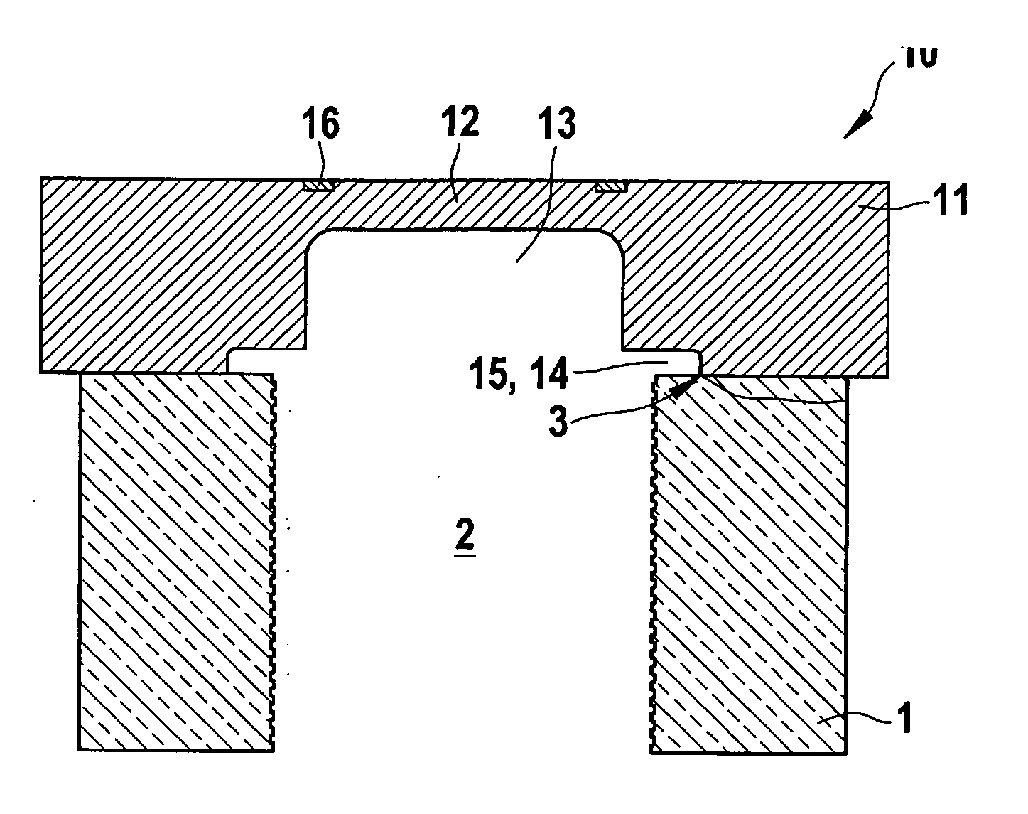
[0022]Sensor system 10 represented in FIG. 1 is used for detecting high pressures. To that end, sensor system 10 includes a micromechanical sensor element 11 which is situated on a support 1 having a passage opening 2. Sensor element 11 is mounted, for example, in a housing or on a mounting base via support 1, support 1 being used for reducing the occurring mechanical stresses.

[0023]Sensor element 11 is a silicon chip, a diaphragm 12 being formed in its upper surface having piezoresistive transducer elements 16 for signal detection. However, sensor element 11 may also be made from another semiconductor material. Diaphragm 12 spans a cavern 13 which is produced by trench etching of the chip's rear surface.

[0024]Support 1 is a glass support 1 having a smooth, defect-free upper surface which is largely free from microdefects. Passage opening 2 in glass support 1 is implemented in the form of a bore 2. Accordingly, the walls of passage opening 2 are rough and have micro-cracks. Sensor e...


PUM

PropertyMeasurementUnit
pressuresaaaaaaaaaa
shapeaaaaaaaaaa
areaaaaaaaaaaa

Abstract

A sensor system for detecting high pressures includes a micromechanical sensor element which is situated on a support and is mounted via this support. A diaphragm is formed in the upper surface of the sensor element, the diaphragm spanning a cavern having a rear opening. The support has a passage opening and is connected to the rear side of the sensor element in such a way that the passage opening opens into the rear opening of the cavern. An annular recess is formed in the rear side of the sensor element, the annular recess being situated above the edge area of the passage opening, so that the joining surface between the sensor element and the support does not extend to the edge of the passage opening.

Description

BACKGROUND OF THE INVENTION[0001]1. Field of the Invention[0002]The present invention relates to a sensor system for detecting high pressures having a micromechanical sensor element which is situated on a support and is mounted via this support, for example, on a metal base or in a housing. A diaphragm is formed in the upper surface of the sensor element, the diaphragm spanning a cavern having a rear opening. The support has a passage opening and is connected to the rear side of the sensor element in such a way that the passage opening opens into the rear opening of the cavern.[0003]2. Description of Related Art[0004]A sensor system of this type having a silicon chip as a sensor element is described in published German patent application DE 10 2004 006 199 A1. A diaphragm is formed in the chip upper surface into which the piezoresistors for signal detection are integrated. The diaphragm was formed in this case by etching the rear side of the chip substrate. Accordingly, the diameter...

Claims


Application Information

Patent Timeline
Patent Type & Authority Applications(United States)
IPC IPC(8): G01L7/08
CPCG01L9/0042G01L7/082
Inventor AHLES, MARCUSBENZEL, HUBERT
Owner ROBERT BOSCH GMBH
Why Eureka
Try Eureka