Supercharge Your Innovation With Domain-Expert AI Agents!

System and Process for Optimal Payment Rate Calculation for Diagnostic CPT Code Reimbursement

a diagnostic cpt code and optimal payment technology, applied in the field of system and process for optimal payment rate calculation of diagnostic cpt code reimbursement, can solve the problems of medical providers utilizing older expensive diagnostic equipment and receiving 100% payment, no true input of “useful life” for medical and medicaid services (cms), and many providers using medical “expensive” diagnostic equipmen

Inactive Publication Date: 2014-08-14
CDL NUCLEAR TECH
View PDF3 Cites 0 Cited by
  • Summary
  • Abstract
  • Description
  • Claims
  • Application Information

AI Technical Summary

Benefits of technology

The invention provides a technique and apparatus for calculating the optimal payment rate for medical diagnostic equipment based on its useful life. This is done by receiving audit information for each facility using such equipment, storing the equipment information in a database, and calculating the percentage loss in allowed reimbursement based upon an actual useful life calculation. The percentage loss can be zero during the useful life of the equipment or greater than zero after it. The calculating can be done using a processor and can involve discretely or continuously increasing losses after the useful life of the equipment. The invention helps ensure that medical diagnostic equipment is reimbursed accurately for its actual useful life.

Problems solved by technology

However, currently Medicare and Medicaid Services (CMS) provides for no true input of “useful life” and assumes every 5 years providers purchase new equipment equal to the Practice Expense Advisory Committee (PEAC) input. FIG. 4 shows the CMS reimbursement formula 400 on a per minute basis; and FIG. 5 shows the Medicare fixed costs computation 500 of annual amortized fixed costs for imaging equipment.
However, many providers continue to utilize medical “expensive” diagnostic equipment far beyond the 5 year CMS mandated formula.
This results in medical providers utilizing older expensive diagnostic equipment and receiving 100% payment.
This discourages medical providers from seeking and obtaining the latest and most advanced equipment.
Currently, there is no process or system to track the age of the expensive diagnostic equipment and correct payment based on equipment age.

Method used


Image

  • System and Process for Optimal Payment Rate Calculation for Diagnostic CPT Code Reimbursement
  • System and Process for Optimal Payment Rate Calculation for Diagnostic CPT Code Reimbursement
  • System and Process for Optimal Payment Rate Calculation for Diagnostic CPT Code Reimbursement

Examples


Embodiment Construction

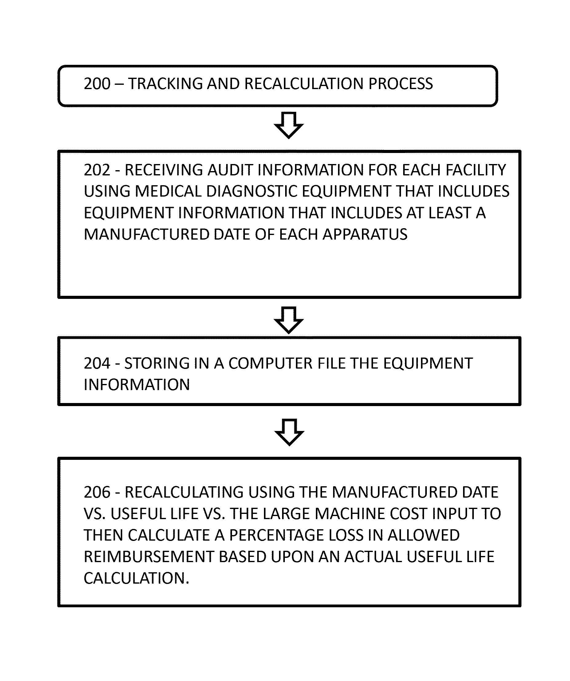
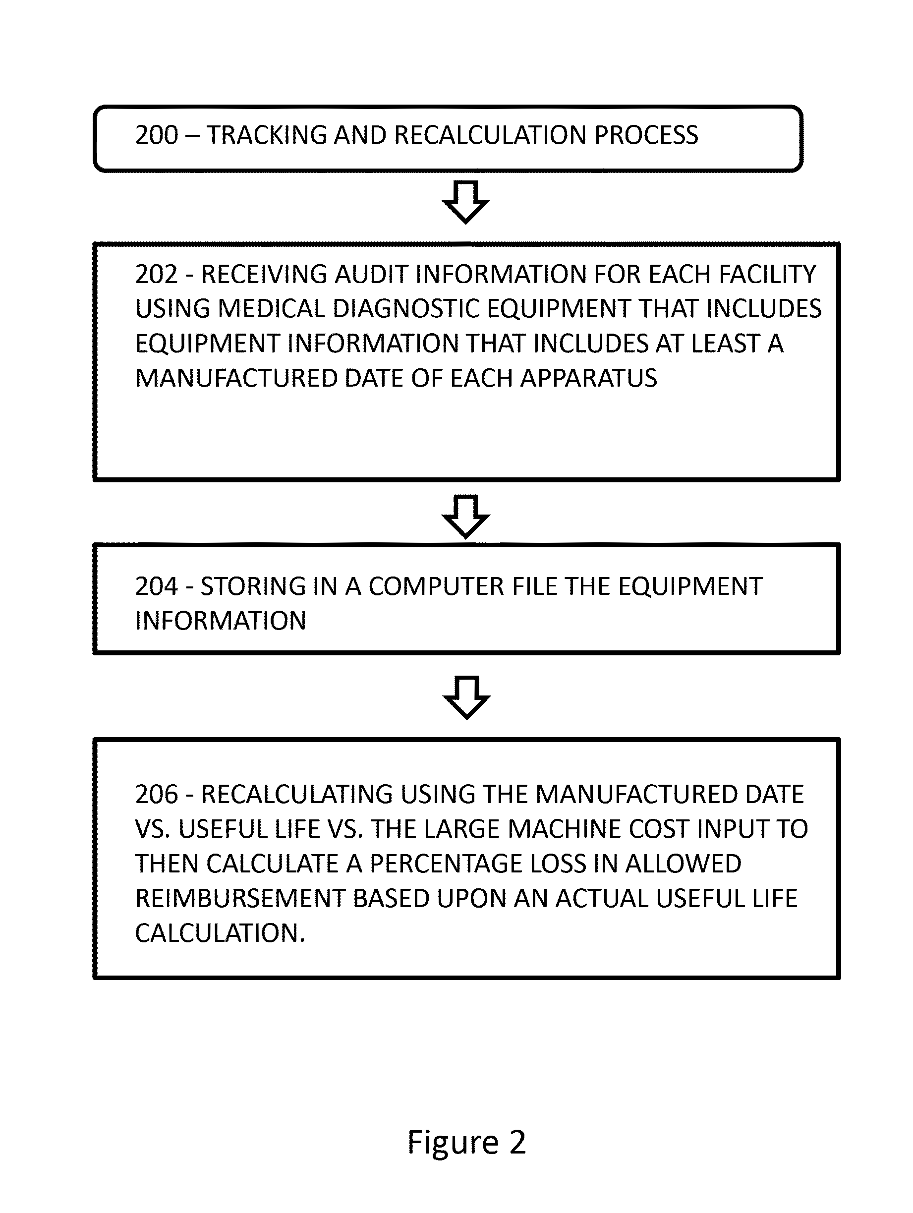
[0021]The invention will now be described with reference to the drawing figures, in which like reference numerals refer to like parts throughout. Embodiments of the invention advantageously provide a mathematical computer computation of a correct payment based on the useful life of medical diagnostic “expensive” equipment.

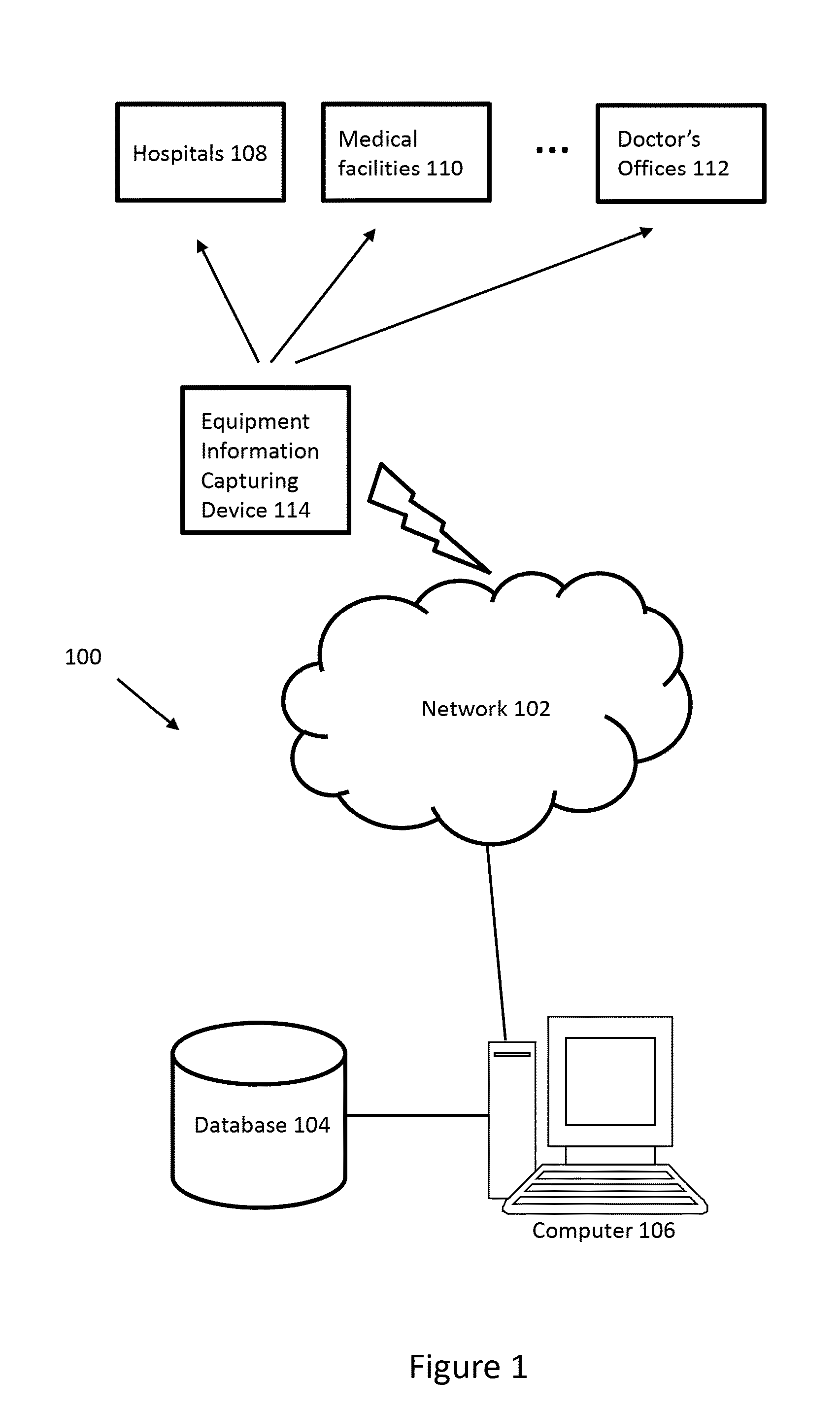
[0022]FIG. 1 is directed to a system for tracking expensive medical diagnostic equipment according to one aspect of the invention. As shown in FIG. 1, hospitals 108, medical facilities 110, doctor's offices 112 and the like may utilize expensive medical diagnostic equipment. An equipment information capturing device 114 may be utilized to capture information regarding the expensive medical diagnostic equipment located at hospitals 108, medical facilities 110, doctor's offices 112 and the like. Thereafter, the information captured by the equipment information capturing device 114 may be transmitted to a computer 106 and a database 104. The computer 106 and the datab...


PUM


Abstract

A process and system for an optimal payment rate calculation of medical diagnostic equipment includes receiving in a processor audit information for each facility using medical diagnostic equipment that includes equipment information that comprises at least a manufactured date of each medical diagnostic device. The system then process further including storing the equipment information in a database and calculating a percentage loss in allowed reimbursement based upon an actual useful life calculation in the processor.

Description

CROSS-REFERENCE TO RELATED APPLICATIONS[0001]This application claims the benefit from U.S. Provisional Application No. 61 / 763,851 filed on Feb. 12, 2013, which is hereby incorporated by reference in its entirety for all purposes as if fully set forth herein.FIELD OF THE INVENTION[0002]The invention relates to a system and process for tracking medical diagnostic “expensive” equipment and recalculating the reimbursement formula to allow for the input of a mathematical computer computation of the correct payment, based on the useful life of medical diagnostic “expensive” equipment. The invention also relates to a system and process for tracking medical diagnostic “expensive” equipment and recalculating the centers for Medicare and Medicaid Services (CMS) reimbursement formula, which is the standard for Current Procedural Terminology (CPT) code reimbursement to hospitals and physicians, to allow for the input of a mathematical computer computation of the correct payment, based on the us...

Claims


Application Information

Patent Timeline
IPC IPC(8): G06Q50/22G06Q30/02G16H40/40
CPCG06Q50/22G06Q30/0283G16H40/40G06Q10/10
Inventor WILSON, LON PATRICK
Owner CDL NUCLEAR TECH
Features
  • R&D
  • Intellectual Property
  • Life Sciences
  • Materials
  • Tech Scout
  • Unparalleled Data Quality
  • Higher Quality Content
  • 60% Fewer Hallucinations
Learn More