Dynamic tool control in a digital graphics system using a vision system

a vision system and tool control technology, applied in the field of graphic computer software systems, can solve the problems of time-consuming navigating the guis, requiring a significant learning curve to master, and the complexity of the user interface menu

Inactive Publication Date: 2014-08-14
COREL CORP
View PDF9 Cites 19 Cited by
  • Summary
  • Abstract
  • Description
  • Claims
  • Application Information

AI Technical Summary

Benefits of technology

[0005]In one aspect of the invention, a method for controlling tool selection in a graphics application program executing on a computer is disclosed. The method includes a step of connecting a vision system to the computer, wherein the vision system is adapted to monitor a visual space. The method further includes the steps of detecting, by the vision system, a tracking object in the visual space, executing, by the computer, a graphics application program, and outputting, by the vision system to the computer, spatial coordinate data representative of the location of the tracking object within the visual space. The method further includes the steps of mapping a horizontal portion and a vertical portion of the spatial coordinate data to a display connected to the computer, and entering a tool configuration utility user interface within the graphics application program. A characteristic of a tool within the tool configuration utility user interface is controlled by mapping the spatial coordinate data to a tool control.
[0006]In another aspect of the invention, a graphic computer software system is disclosed. The system includes a computer comprising one or more processors, one or more computer-readable memories, an...

Problems solved by technology

As the choices available to the user increase, so does the complexity of the user interface menu.
However, with the ever-increasing...

Method used


Image

  • Dynamic tool control in a digital graphics system using a vision system
  • Dynamic tool control in a digital graphics system using a vision system
  • Dynamic tool control in a digital graphics system using a vision system

Examples


example 2

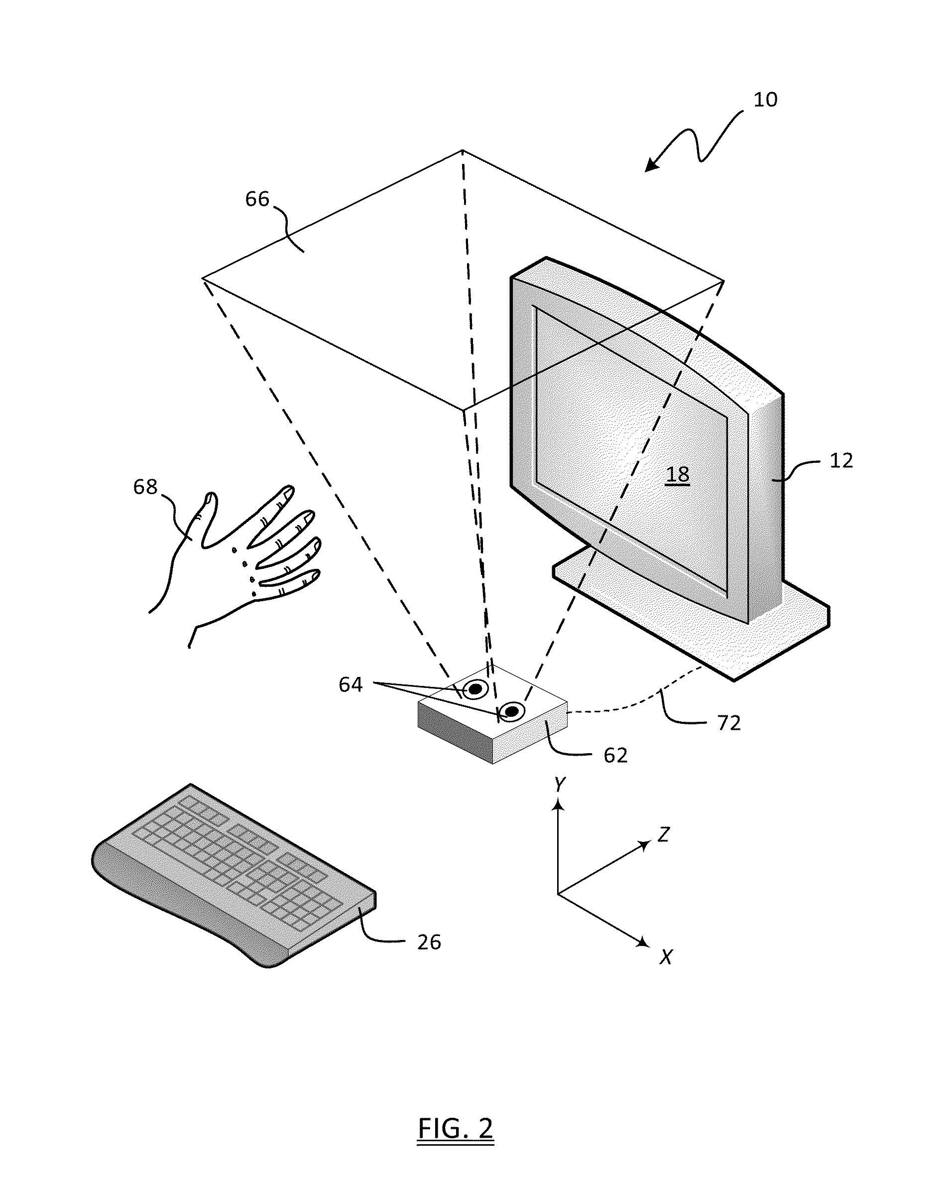
[0066] The orientation of the tracking object 68 can be used to control one or more tool parameters. The vision system 62 can be calibrated or otherwise adapted to recognize a plurality of points on a given tracking object 68, the size of the tracking object, or the shape and geometry of the tracking object. In this manner, a general shape or outline of each tracking object 68 can be exported to the computer 12 as three-dimensional coordinate data, and the data can be processed to calculate if the tracking object 68 is straight or tilted, or if the tracking object 68 matches pre-defined profiles 70 such as hand gestures.

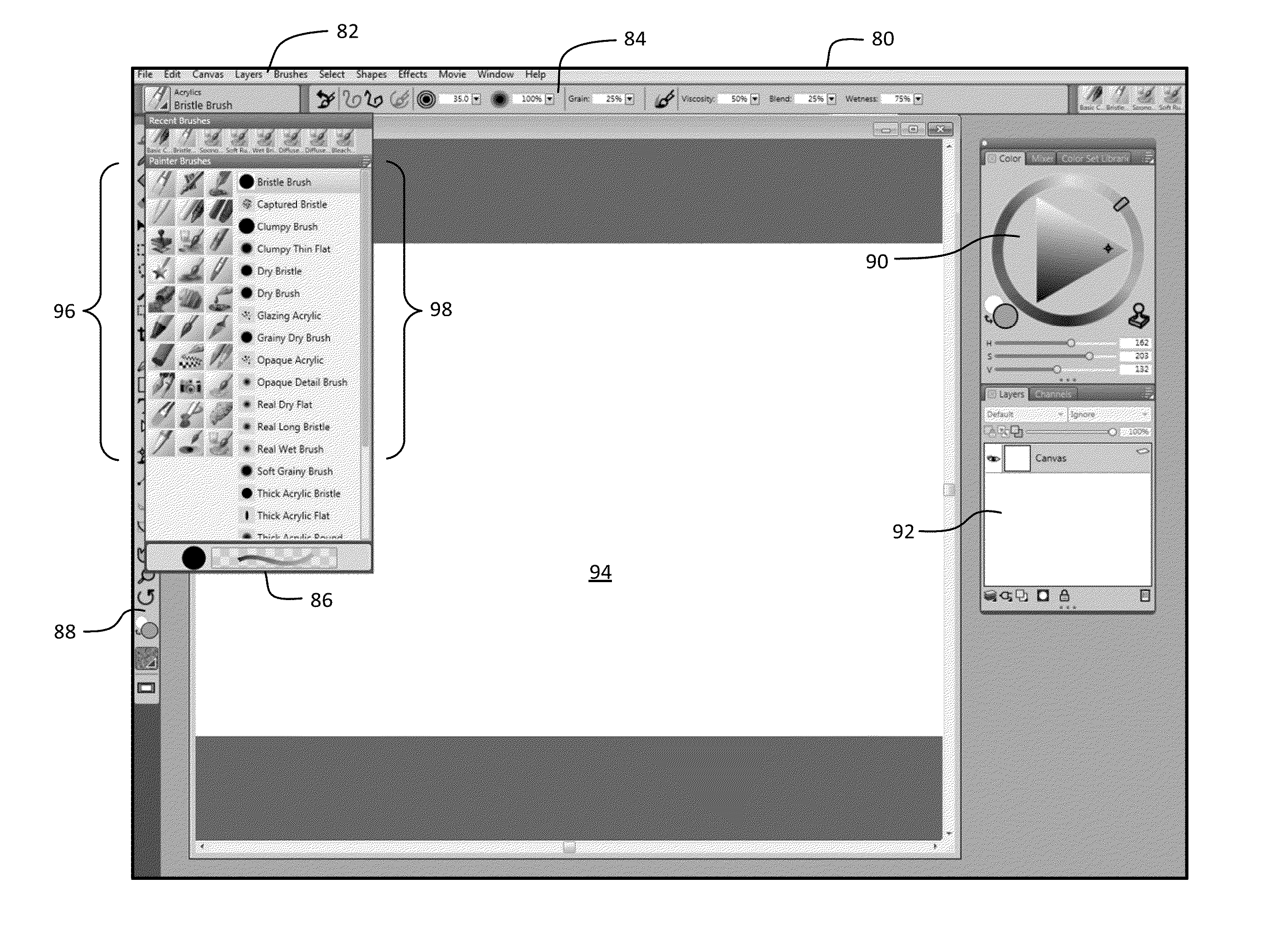
[0067]In some painting applications, the degree of tilt is a brush parameter that can be set by way of a pulling up a menu and adjusting a slider bar, typically between 0 and 90 degrees. The brushstroke will appear as though the tool was tilted at the defined angle, which has a pronounced effect when using an airbrush. Other similar parameters that can be changed inc...


PUM


Abstract

A system and method for controlling tool selection in a graphics application program executing on a computer are disclosed. The method includes the steps of connecting a vision system to the computer, wherein the vision system is adapted to monitor a visual space. The method further includes the steps of detecting, by the vision system, a tracking object in the visual space, and outputting, by the vision system to the computer, spatial coordinate data representative of the location of the tracking object within the visual space. The method further includes the steps of mapping a horizontal portion and a vertical portion of the spatial coordinate data to a display connected to the computer, and controlling a characteristic of a tool within the tool configuration utility user interface by mapping the spatial coordinate data to a tool control.

Description

FIELD OF THE INVENTION[0001]This disclosure relates generally to graphic computer software systems and, more specifically, to a system and method for creating and controlling computer graphics and artwork with a vision system.BACKGROUND OF THE INVENTION[0002]Graphic software applications provide users with tools for creating drawings for presentation on a display such as a computer monitor or tablet. One such class of applications includes painting software, in which computer-generated images simulate the look of handmade drawings or paintings. Graphic software applications such as painting software can provide users with a variety of drawing tools, such as brush libraries, chalk, ink, and pencils, to name a few. In addition, the graphic software application can provide a ‘virtual canvas’ on which to apply the drawing or painting. The virtual canvas can include a variety of simulated textures.[0003]To create or modify a drawing, the user selects an available input device and opens a...

Claims


Application Information

Patent Timeline
IPC IPC(8): G06F3/0484
CPCG06F3/0484G06F3/017G06F3/0304G06F3/0346
Inventor TREMBLAY, CHRISTOPHER J.BOLT, STEPHEN P.
Owner COREL CORP
Why Eureka
Try Eureka