
Multi-view 3D image display apparatus using modified common viewing zone

a 3d image and display apparatus technology, applied in the direction of electrical apparatus, color television details, pictoral communication, etc., can solve the problems of difficult to implement natural 3d images while a viewer, non-uniform crosstalk of 3d image display apparatus, and difficulty in implementing natural 3d images, etc., to achieve uniform brightness and low crosstalk. uniform

Active Publication Date: 2014-08-21
KOREA INST OF SCI & TECH
View PDF11 Cites 21 Cited by
  • Summary
  • Abstract
  • Description
  • Claims
  • Application Information

AI Technical Summary

Benefits of technology

The present invention is a display that can show multiple views of 3D images without causing brightness or crosstalk issues for the viewer. This is achieved by modifying the way the images are viewed so that they appear uniform regardless of the viewer's position.

Problems solved by technology

Thus, it is difficult to implement natural 3D images while a viewer is moving, thereby giving the viewer an uncomfortable feeling.
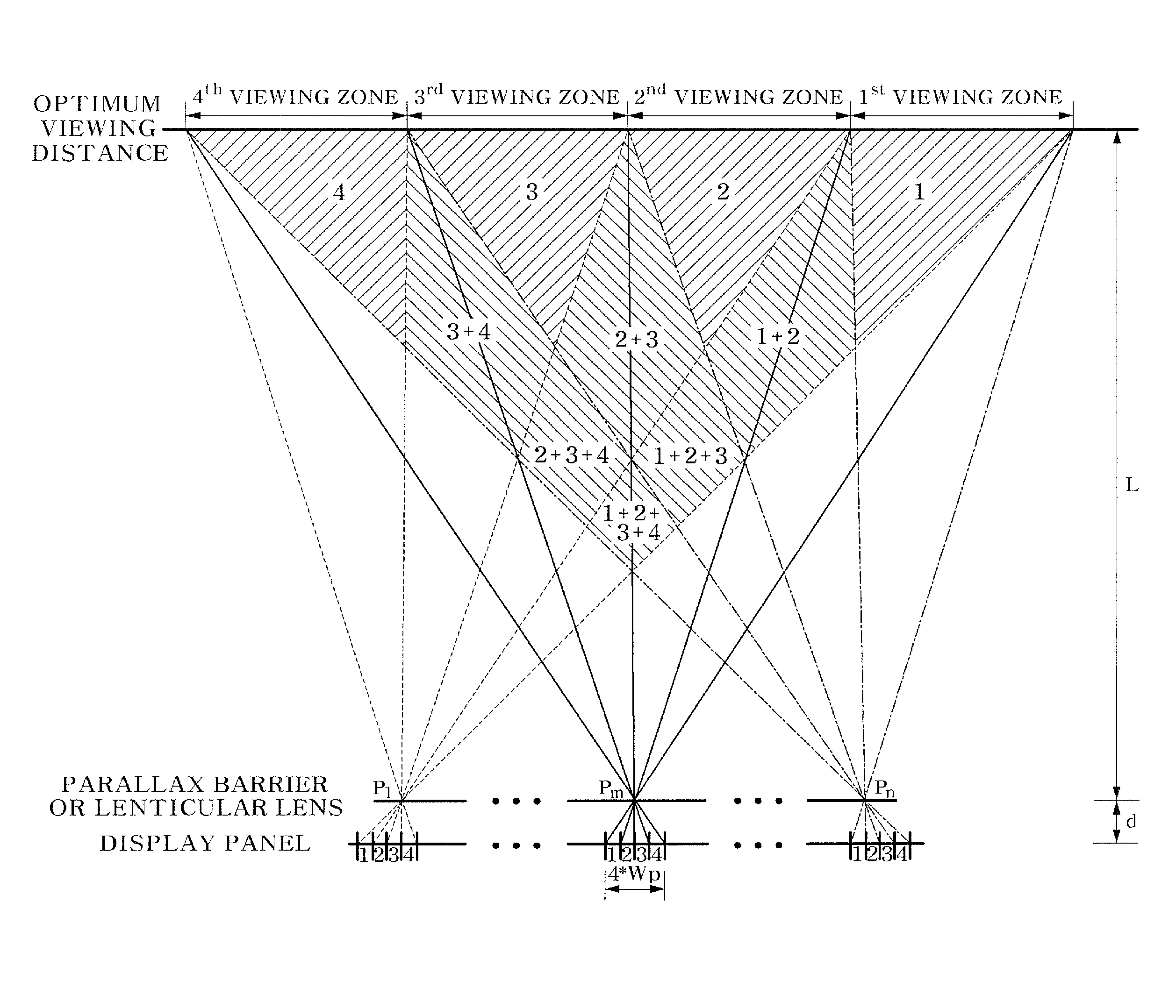
However, such a general multi-view 3D image display apparatus may have a problem of a nonuniform amount of crosstalk that changes with horizontal movement (movement parallel to the display panel) of the viewer.
In addition, there is also a problem of an absolute value of the minimized crosstalk quantity being larger than a general amount of crosstalk in a method using glasses.
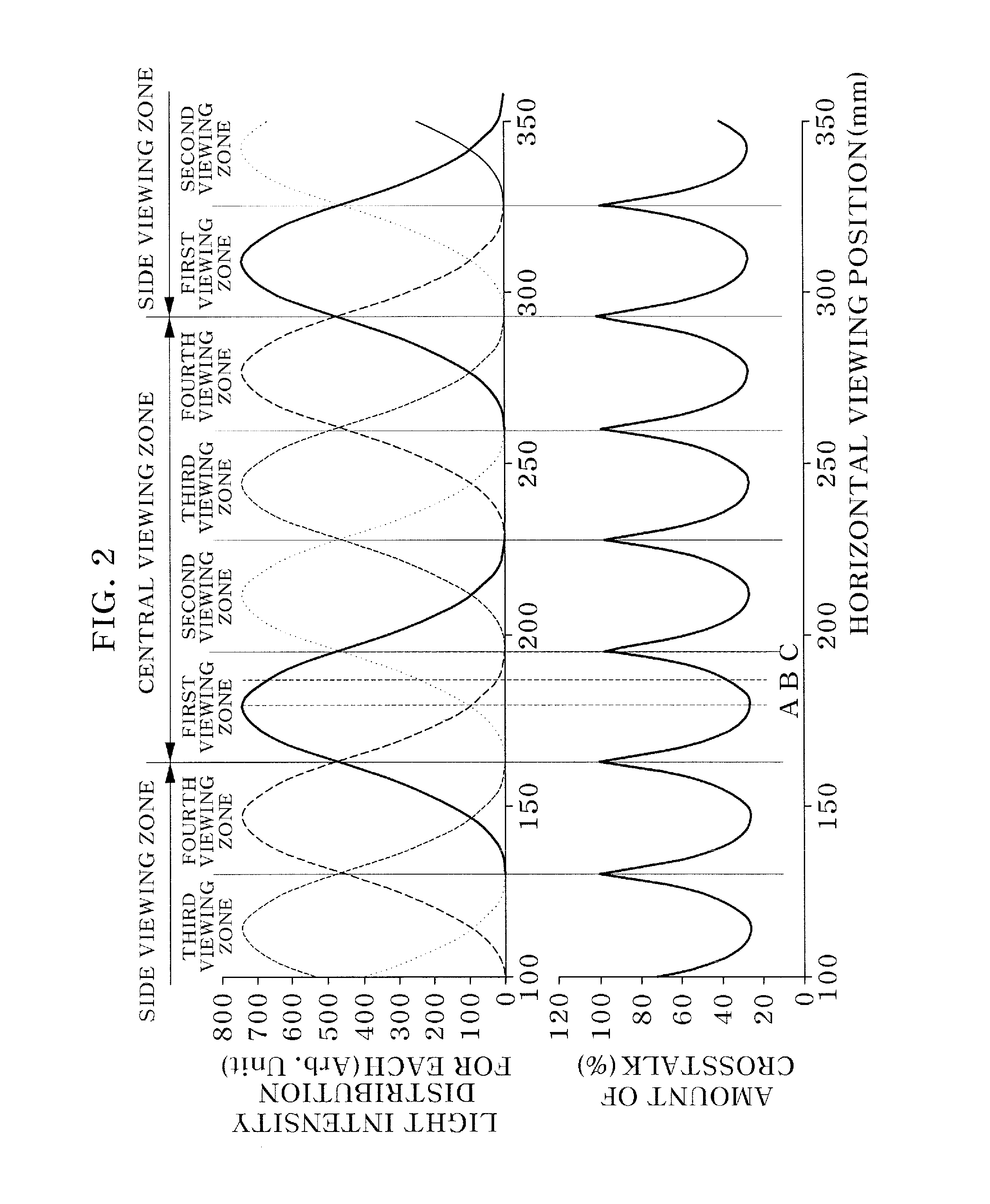
As shown in FIG. 2, viewing zone characteristics of the general multi-view 3D image display apparatus have a problem in that brightness of a corresponding viewpoint image changes depending on the horizontal position of the viewer.
In addition, an amount of crosstalk of about 20% to 30% may be generated even when the pupil of the viewer is positioned at the center of the viewing zone, and therefore there is a disadvantage of the amount of crosstalk being at least four times larger than in a general glasses type 3D image display apparatus (average amount of crosstalk is 5% or less).
In such an integral photography method, an amount of crosstalk within a central viewing zone is uniform, but as shown in FIG. 3, there are disadvantages in that a range of the central viewing zone is reduced compared to the multi-view method and an average amount of crosstalk within the central viewing zone is large.
As described above, crosstalk that occurs in the autostereoscopic 3D image display apparatus is an important issue in commercialization.

Method used


Image

  • Multi-view 3D image display apparatus using modified common viewing zone
  • Multi-view 3D image display apparatus using modified common viewing zone
  • Multi-view 3D image display apparatus using modified common viewing zone

Examples


first embodiment

[0060]A concept of the modified common viewing zone according to a first embodiment of the present invention will be described with reference to FIGS. 4A to 4C. FIGS. 4A to 4C are conceptual diagrams explaining a modified common viewing zone range according to a first embodiment of the present invention. FIG. 4A shows a size of a central viewing zone (common viewing zone) of the multi-view 3D image display apparatus, and “N (the number of viewpoints)*UVZ (unit viewing zone)” may be derived from this. FIG. 4B shows a size of a central viewing zone of the 3D image display apparatus employing the integral photography method, and “N*UVZ−SZ (size of horizontal display)” may be derived from this. Thus, the size of the central viewing zone of the 3D image display apparatus employing the integral photography method is significantly smaller than the size of the central viewing zone (common viewing zone) of the multi-view 3D image display apparatus. A range of the central viewing zone of the ...

second embodiment

[0096]Hereinafter, concept of a modified common viewing zone according to a second embodiment of the present invention will be described with reference to FIGS. 17 to 19.

[0097]In the method of using the modified common viewing zone which has been described with reference to FIGS. 4, 6, and 8, a modified viewing zone having a central viewing zone range between methods of creating the common viewing zone of the multi-view 3D image display apparatus and a parallel viewing zone of the integral photography method may be used. This has the same meaning as using a previous area of an OVD in the general multi-view 3D design as shown in FIG. 17. However, in this case, a depth direction distance is limited and the modified common viewing zone range should be smaller than the central viewing zone range in the OVD.

[0098]In the second embodiment of the present invention using the modified common viewing zone that can overcome such limitations, an area of the modified common viewing zone beyond t...


PUM


Abstract

Disclosed is a multi-view three-dimensional (3D) image display apparatus using a modified common viewing zone. The multi-view 3D image display apparatus may use a modified common viewing zone between a central viewing zone (common viewing zone) of the multi-view 3D image display apparatus and a central viewing zone (parallel viewing zone) of a 3D image display apparatus employing an integral photography method, or form a common viewing zone at an optimum viewing distance (OVD) of the multi-view 3D image display apparatus and use a modified common viewing zone in an area beyond the OVD.

Description

CROSS-REFERENCE TO RELATED APPLICATION[0001]This application claims priority to and the benefit of Korean Patent Application No. 2013-0017678, filed on Feb. 19, 2013, the disclosure of which is incorporated herein by reference in its entirety.BACKGROUND[0002]1. Field of the Invention[0003]The present invention relates to a multi-view three-dimensional (3D) image display apparatus, and more particularly, to a multi-view 3D image display apparatus which may form a modified common viewing zone corresponding to an intermediate concept of a multi-view 3D image display apparatus and an integrated 3D image display apparatus, or equalize or reduce an amount of crosstalk using a predetermined region after the common viewing zone created at an optimum viewing distance (OVD) of the multi-view 3D image display apparatus.[0004]2. Discussion of Related Art[0005]An autostereoscopic multi-view three-dimensional (3D) image display apparatus may employ a method using an optical plate such as a lentic...

Claims


Application Information

Patent Timeline
IPC IPC(8): H04N13/04
CPCH04N13/0409H04N13/0479H04N13/0404H04N13/31H04N13/305H04N13/376
Inventor KIM, SUNG KYUYOON, KI HYUK
Owner KOREA INST OF SCI & TECH
Learn More