Drainable sight glass and associated methods

a sight glass and associated technology, applied in the field of sight glass and associated methods, can solve the problems of sight glass body, sight glass vulnerable to cracking and shattering, and difficulty in viewing oil for inspection and water to separate for draining from the bottom valv

Active Publication Date: 2014-08-28
SAUDI ARABIAN OIL CO
View PDF7 Cites 19 Cited by
  • Summary
  • Abstract
  • Description
  • Claims
  • Application Information

AI Technical Summary

Benefits of technology

[0014]Embodiments of a method for using a sight glass with a pump housing to monitor the condition of oil in the pump housing and to drain water from such a housing are described herein, also. Such a method can comprise connecting an upper valve positioned in a sight glass housing to the drain port of the housing, the sight glass housing having a top side with a large diameter top opening sealed with a upper disk layer having a threaded receptacle formed therein for receiving the upper valve, a bottom side with a small diameter bottom opening sealed with a lower disk portion sized substantially similarly to the upper disk layer and having a second threaded receptacle formed therein for receiving a lower valve, a lower valve connected to the drainable sight glass assembly at the second threaded receptacle, the lower valve having a valve housing with threads to engage the second threaded receptacle and a stem, a top portion of the stem being disposed in the valve housing and another bottom portion of the stem being positioned on the exterior of the sight glass and connected to a handle, the top portion of the stem having at least on opening formed therein so that when the top portion of the stem is disposed substantially inside the housing, the at least one opening is not exposed to the frustoconically shaped interior of the sight glass housing, and when the top portion of the stem is positioned so that the top portion of the stem is disposed outside of the valve housing in the frustoconical interior of the sight glass, the at least one opening is exposed to the frustoconically shaped interior, and a substantially transparent wall portion connecting the top side to the bottom side and the large diameter top opening to the small diameter bottom opening so that the sight glass has a hollow, substantially frustoconically shaped interior when fluid is not in the drainable sight glass assembly; draining oil into the sight glass using the upper valve in conjunction with the housing drain port; viewing the contents of the sight glass to determine the condition of the oil in the sight glass and whether or not water is present; and turning the lower portion of the stem handle of the lower valve when it is determined that water is in the sight glass to expose the top portion of the stem being disposed substantially inside the valve housing to the interior of the frustoconically shaped sight glass interior to drain water from the sight glass.

Problems solved by technology

Unfortunately, contaminants in the motor housing, e.g., dirt, can create a turbulent flow into and a sludge in the sight glass body making it difficult to view the oil for inspection and for water to separate from the oil for draining from the bottom valve.
In addition, the creation of a sludge in the sight glass body can, over time, weaken the sight glass body, making the sight glass vulnerable to cracking and shattering.
Moreover, if the piping to the sight glass gets clogged, there can be a false indication of oil condition, e.g., the oil in the sight glass can appear clean and pristine contrary to the condition of the oil in the sump.
This sight glass includes a top and bottom valve connects to a tubular shaped, transparent sight glass body, and therefore presents the same problems to the operator as those noted.
There are no valves in Schachinger to allow for water to drain from the sight glass, and the pump housing, and accordingly, Schachinger cannot solve the problems noted above.
Martin also does not have valves for draining water from the sight glass and housing, and accordingly cannot solve the problems in the art noted above.

Method used


Image

  • Drainable sight glass and associated methods
  • Drainable sight glass and associated methods
  • Drainable sight glass and associated methods

Examples


Embodiment Construction

[0044]The present invention will now be described more fully hereinafter with reference to the accompanying drawings in which embodiments of the invention are shown. This invention can, however, be embodied in many different forms and should not be construed as limited to the illustrated embodiments set forth herein; rather, these embodiments are provided so that this disclosure will be thorough and complete, and will fully convey the scope of the invention to those skilled in the art.

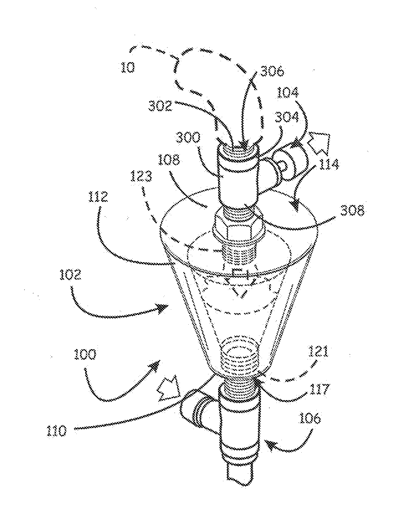
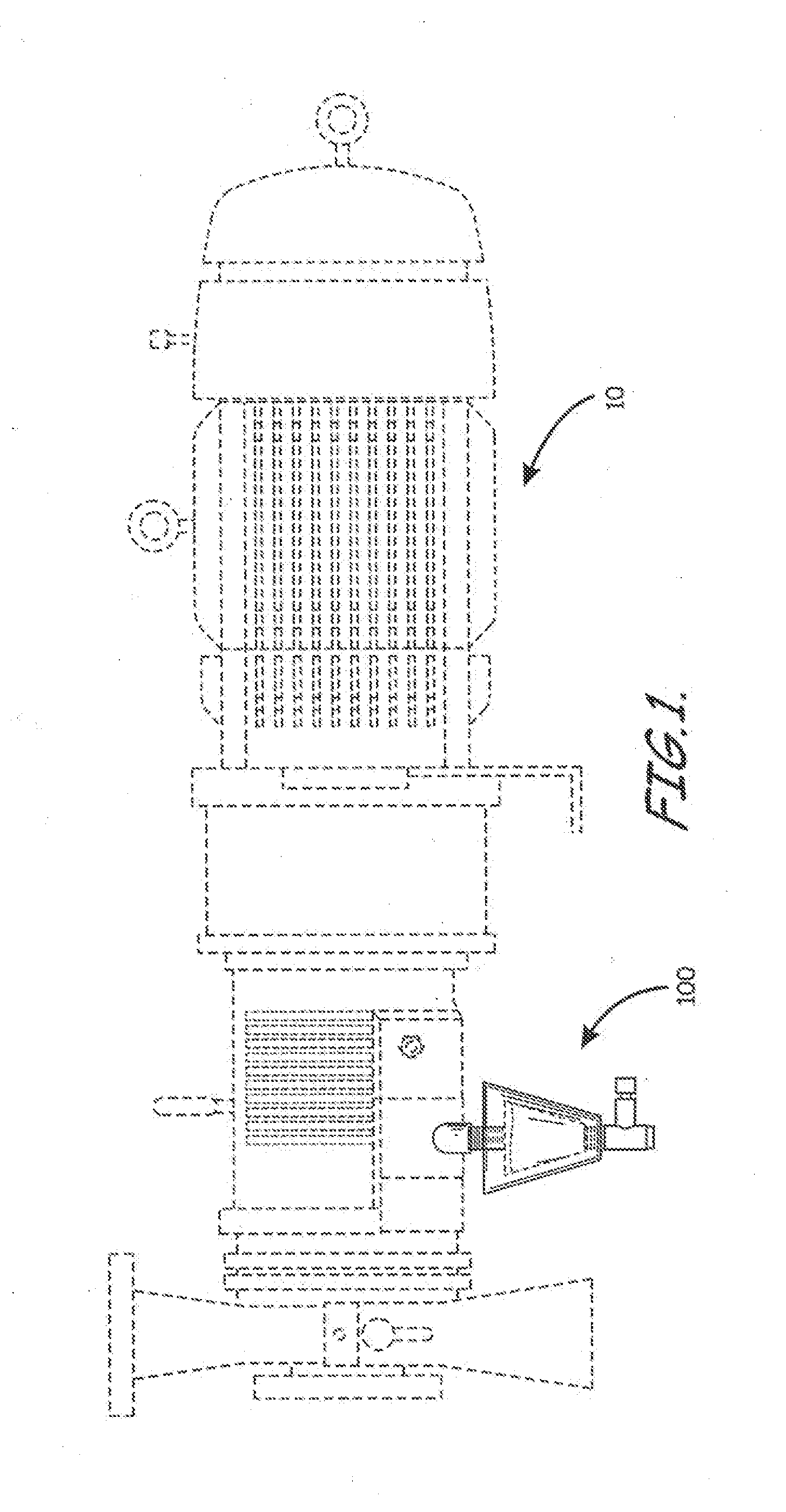
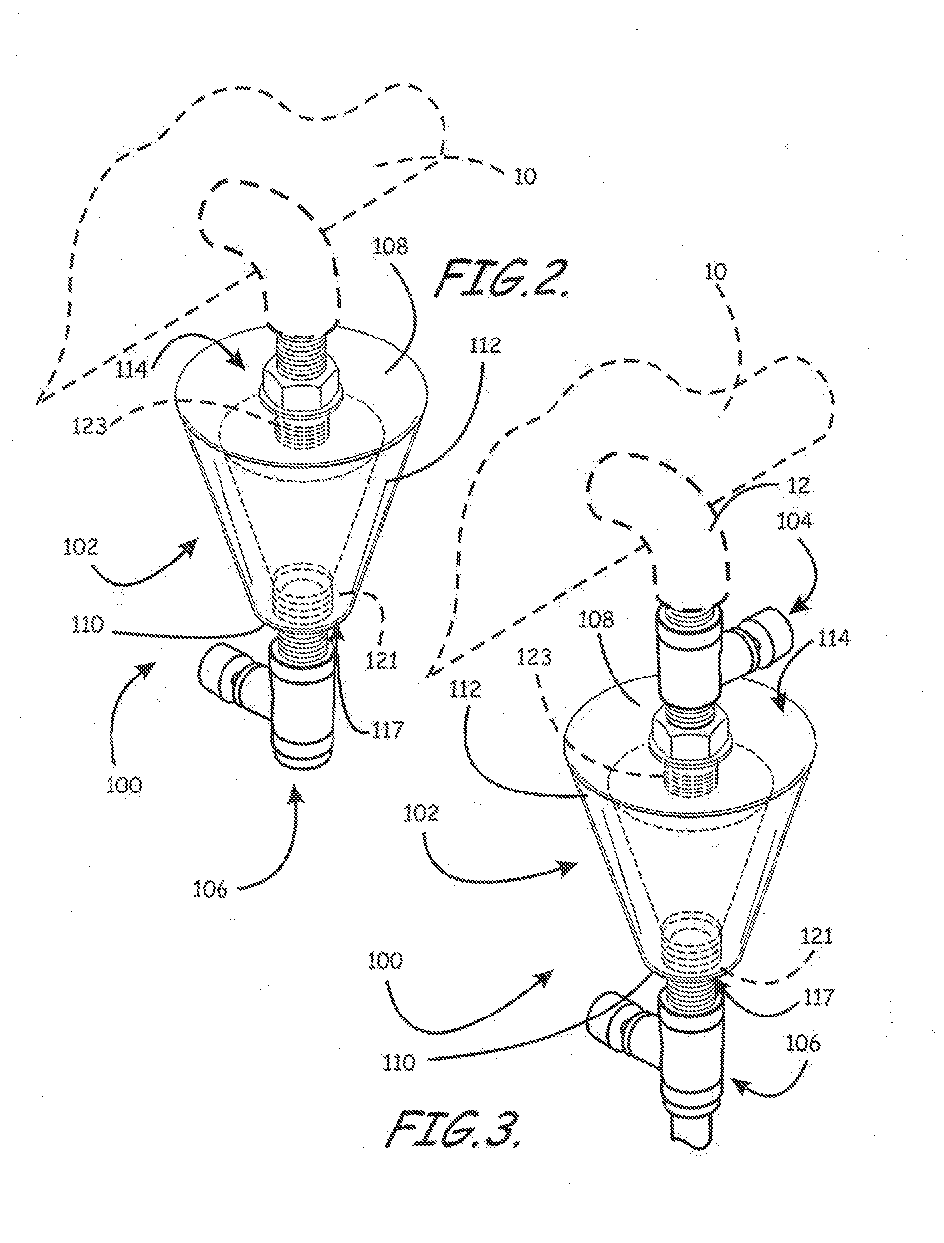
[0045]Embodiments of the invention are directed to a frustoconically-shaped, drainable sight glass and associated methods such as to install on or use in association with fluid lubricating machinery to assist in determining the condition of fluid in the vessel. For example, the sight glass can be used to monitor the condition of oil in a lubrication system of an industrial pump. An embodiment of a sight glass, for example, can have a sight glass body that includes a sight glass body, for example, a rin...


PUM

PropertyMeasurementUnit
diameteraaaaaaaaaa
diameteraaaaaaaaaa
diameteraaaaaaaaaa

Abstract

Embodiments of the invention are directed to methods of use and a (trainable sight glass assembly for use with a sump pump having a pump housing and being adapted to view the condition of oil disposed, within the pump housing. In some embodiments, the drainable sight glass assembly can comprise a sight glass housing having an upper disk layer with a first diameter and a first threaded receptacle formed therein disposed on a top side of the sight glass housing, a lower disk portion with a second diameter and a second threaded receptacle formed therein and disposed on a bottom side of the sight glass housing, and a substantially transparent wall portion connecting upper disk layer to the lower disk portion so that the sight glass has a hollow, substantially frustoconically shaped interior when oil is not in the sight glass housing.

Description

RELATED APPLICATIONS[0001]This application claims priority to and the benefit of: U.S. Provisional Patent Application Ser. No. 61 / 539,330, by Aljohani, titled “Drainable Sight Glass and Associate Methods” filed Sep. 26, 2011, which is incorporated herein by reference in its entirety.FIELD OF INVENTION[0002]The present invention relates generally to methods and apparatuses for monitoring the condition of oil in a housing, such as a pump motor housing, and more particularly to monitoring oil in a housing a frustoconically shaped sight glass.BACKGROUND OF THE INVENTION[0003]A drainable sight glass assembly and method for installation of such a sight glass on industrial machinery, e.g., oil sumps, oil reservoirs, and diesel fuel tanks, in the art is used to check the condition of oil in a pump or motor housing. In some prior art embodiments, the sight glass can also be used to separate oil and water. Such sight glasses include a top and bottom valve connected to a tubular shaped, transp...

Claims


Application Information

Patent Timeline
Patent Type & Authority Applications(United States)
IPC IPC(8): G01N1/10
CPCG01N1/10G01F23/02
Inventor ALJOHANI, SAMER MOHAMMED
Owner SAUDI ARABIAN OIL CO
Why Eureka
Try Eureka