Humidity sensor diagnostics

a technology of humidity sensor and diagnostics, which is applied in the direction of electric control, combustion engines, machines/engines, etc., can solve the problem that additional humidity sensors may not be available for comparison

Active Publication Date: 2014-08-28
FORD GLOBAL TECH LLC
View PDF11 Cites 35 Cited by
  • Summary
  • Abstract
  • Description
  • Claims
  • Application Information

AI Technical Summary

Problems solved by technology

However, the inventors herein have identified a potential issue with such an approach.
Further, multiple humidity sensors may not be needed for engine control, and thus additional humidity sensors may not be available for comparison.

Method used


Image

  • Humidity sensor diagnostics
  • Humidity sensor diagnostics
  • Humidity sensor diagnostics

Examples


Embodiment Construction

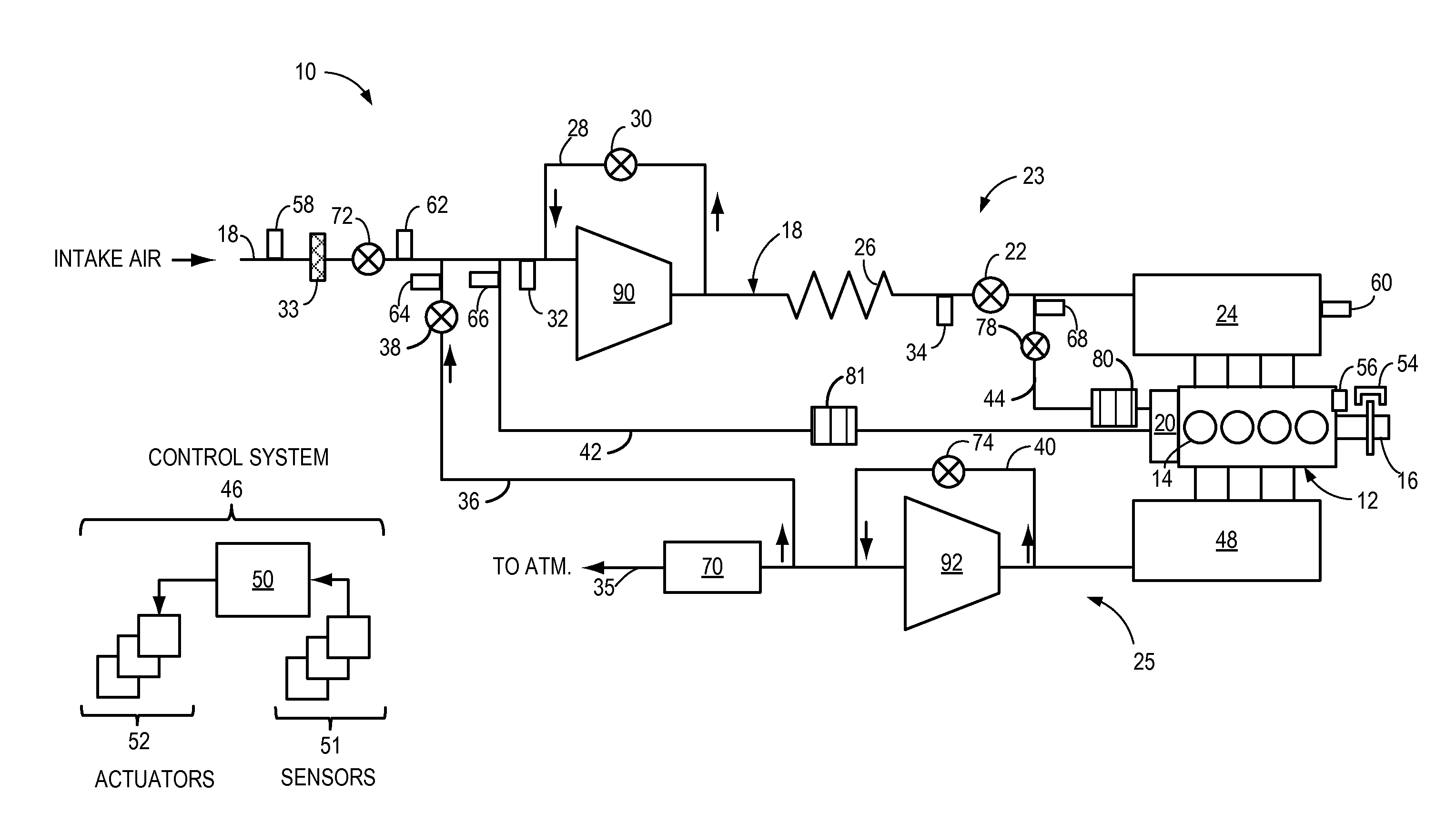
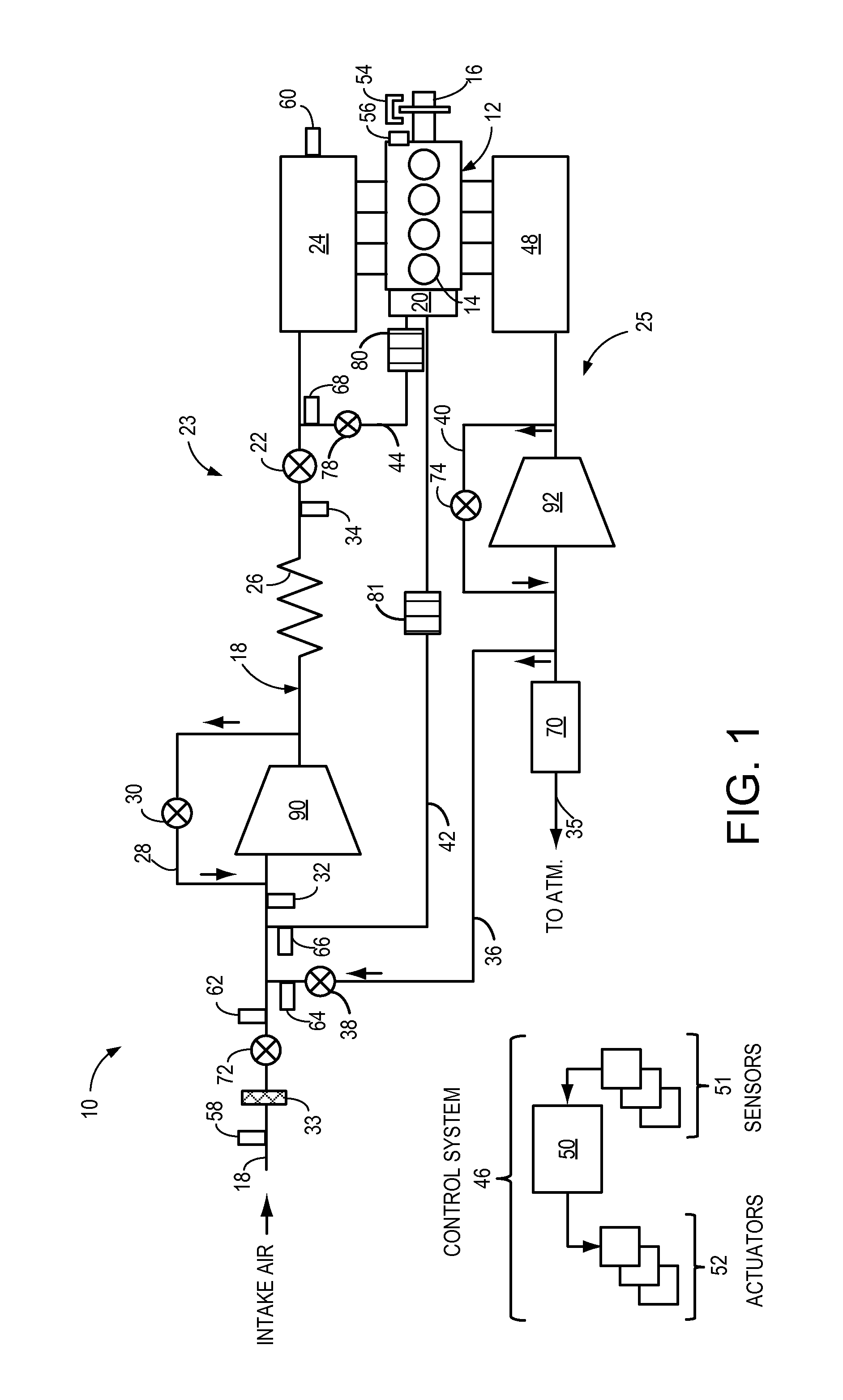
[0016]FIG. 1 shows an example engine system 10 including an engine 12. In the present example, engine 12 is a spark-ignition engine of a vehicle, the engine including a plurality of cylinders 14, each cylinder including a piston. Combustion events in each cylinder 14 drive the pistons which in turn rotate crankshaft 16, as is well known to those of skill in the art. Crankshaft 16 may be housed in a crankcase 20. Further, engine 12 may include a plurality of engine valves, the valves coupled to the cylinders 14 and controlling the intake and exhaust of gases in the plurality of cylinders 14.

[0017]Engine 12 includes an engine intake 23 and an engine exhaust 25. Engine intake 23 includes an engine throttle 22 fluidly coupled to an engine intake manifold 24 along an intake passage 18. Air may enter intake passage 18 from an air intake system (AIS) including an air cleaner 33 in communication with the vehicle's environment and an AIS throttle 72 downstream of air cleaner 33. A position o...


PUM


Abstract

Embodiments for diagnosing a humidity sensor are provided. One example method comprises adjusting an engine operating parameter based on humidity of a first gas flow measured by a humidity sensor, and indicating degradation of the humidity sensor if a humidity of a second gas flow measured by the humidity sensor is different than an expected humidity. In this way, degradation of the humidity sensor may be indicated if the humidity of the second gas flow measured by the humidity sensor is different than expected.

Description

FIELD[0001]The present disclosure relates to humidity sensor diagnostics.BACKGROUND AND SUMMARY[0002]Engine systems may be configured with exhaust gas recirculation (EGR) systems via which at least a portion of the exhaust gas is recirculated to the engine intake. Various sensors may be coupled in the engine system to estimate the amount of EGR being delivered to the engine. These may include, for example, various temperature, pressure, oxygen, and humidity sensors. Since the accuracy of the EGR estimation relies on the correct functioning of the various sensors, periodic sensor diagnostics are used. Further, engines with or without EGR need an estimate of air dilution to optimally set the ignition timing, among other controls. Combustion air dilution may be determined based on humidity measurements using humidity sensors.[0003]One example approach for diagnosing a humidity sensor is illustrated by Xiao et al. in U.S. Pat. No. 7,715,976. Therein, humidity sensor degradation is deter...

Claims


Application Information

Patent Timeline
Patent Type & Authority Applications(United States)
IPC IPC(8): F02D41/22
CPCF02D41/222Y02T10/40F02D2200/0611F02D41/005F02D2200/0418G01N33/0006
Inventor PURSIFULL, ROSS DYKSTRAMAKKI, IMAD HASSANCLARK, TIMOTHY JOSEPHUHRICH, MICHAEL JAMESKUMAR, PANKAJ
Owner FORD GLOBAL TECH LLC
Why Eureka
Try Eureka