
Systems and methods of orienting a cant in lumber mills

a technology of cant orientation and lumber mill, which is applied in the direction of precision positioning equipment, metal-working machine components, manufacturing tools, etc., can solve the problems of lumber mills easily suffering a 1% to 4% loss of value, the system of optimizing systems is complex and expensive, and the management is difficul

Inactive Publication Date: 2014-08-28
WEYERHAEUSER NR CO
View PDF7 Cites 12 Cited by
  • Summary
  • Abstract
  • Description
  • Claims
  • Application Information

AI Technical Summary

Benefits of technology

The patent text describes a method for optimizing the orientation of a cant in a lumber mill to produce boards with the desired width and thickness. The method involves determining the dimensions of the cant and its exposed faces, and calculating the optimal orientation of the cant to produce a board with the closest width to the desired value. This orientation is then provided to a human operator or automated machinery to guide the cutting of the cant. The method takes into account various factors such as the width of the board, the premium for different width categories, and the quality of the board. The technical effect of this method is to improve the efficiency of the lumber mill by optimizing the recovery of boards from the cant, reducing waste and improving the overall quality of the finished boards.

Problems solved by technology

These optimizer systems are very complicated and expensive, and are also difficult to manage properly because of their complexity.
If some portion of an optimizer system is not performing as expected, the lumber mill can easily suffer a 1% to 4% loss of value until the problem is found and fixed.
Thus, significant sums of money may be lost should any one optimizer system not function correctly.
Likewise, small increases in efficiency may significantly reduce the amount of raw resources (e.g., trees), required to produce a given amount of lumber of particular grades and / or dimensions.

Method used


Image

  • Systems and methods of orienting a cant in lumber mills
  • Systems and methods of orienting a cant in lumber mills
  • Systems and methods of orienting a cant in lumber mills

Examples


Embodiment Construction

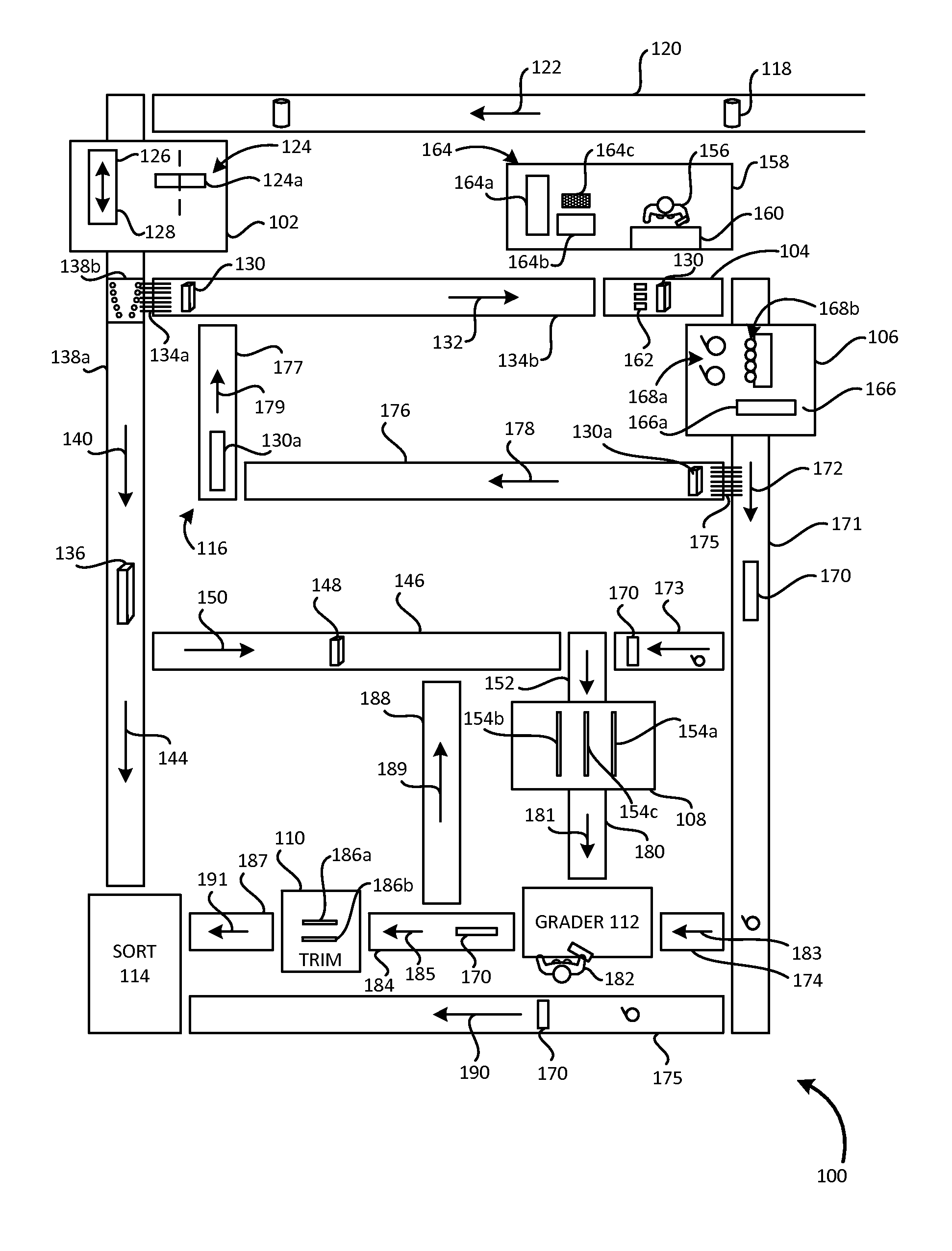
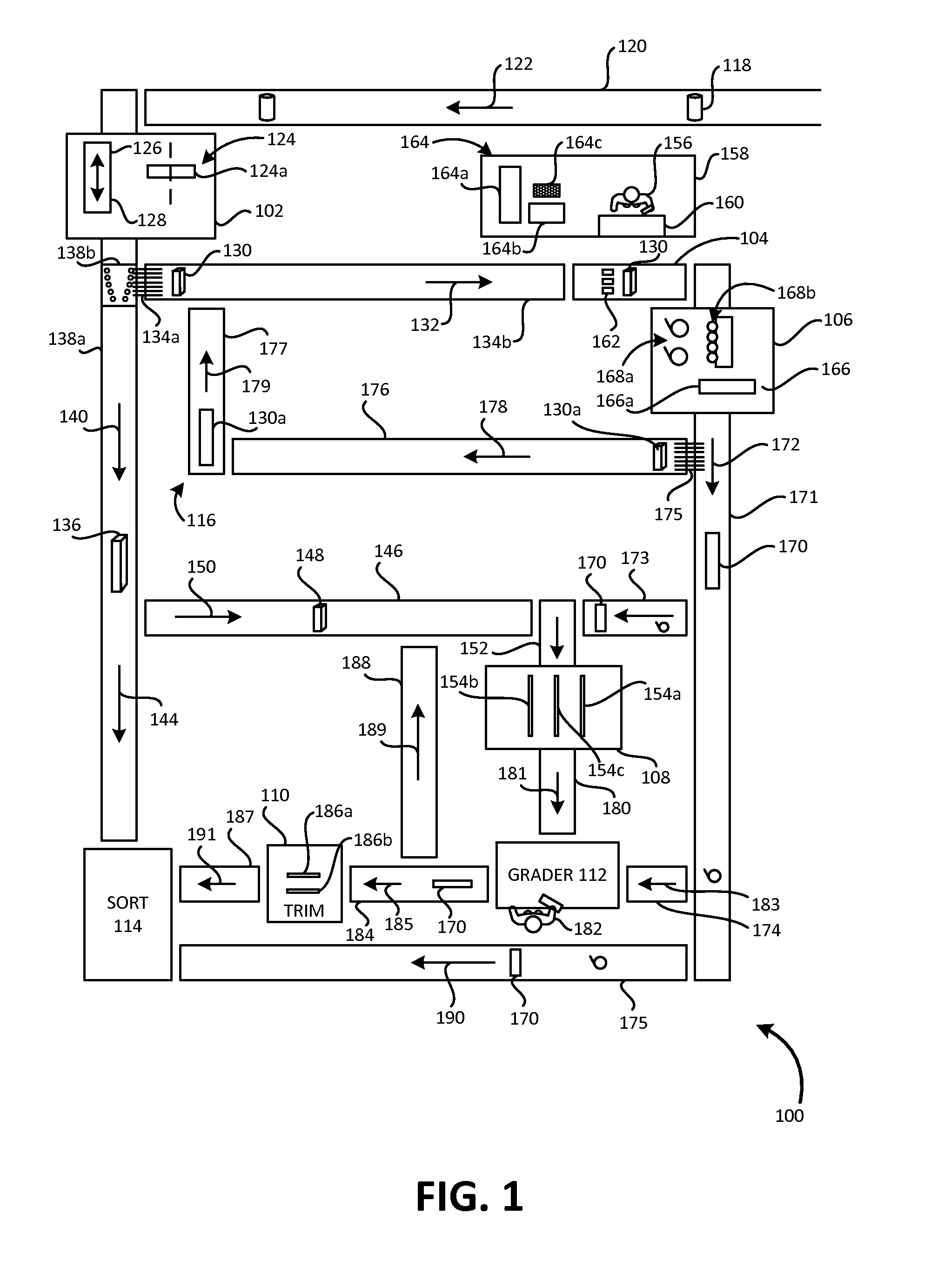
[0043]In the following description, certain specific details are set forth in order to provide a thorough understanding of various disclosed embodiments. However, one skilled in the relevant art will recognize that embodiments may be practiced without one or more of these specific details, or with other methods, components, materials, etc. In other instances, well-known structures associated with lumber mills, head rigs, linebar resaws, edgers, trimmers, saws, conveyors, computing devices, imaging systems and / or laser scanners have not been shown or described in detail to avoid unnecessarily obscuring descriptions of the embodiments.

[0044]Unless the context requires otherwise, throughout the specification and claims which follow, the word “comprise” and variations thereof, such as, “comprises” and “comprising” are to be construed in an open, inclusive sense, that is, as “including, but not limited to.”

[0045]Reference throughout this specification to “one embodiment” or “an embodimen...


PUM

PropertyMeasurementUnit
thickaaaaaaaaaa
thickaaaaaaaaaa
lengthsaaaaaaaaaa

Abstract

Processing of a cant may include determining a rotational orientation about a longitudinal axis of the cant that optimizes a recovery from the cant from subsequent sawing operations. Such may include optimizing a width of a board that will be produced dependent on the particular rotational longitudinal orientation. Such may include determining a surface area of a board which would be produced, a thickness of a board that would be produced, and / or a volume of a board that would be produced. Such may include accounting for any premium associated with various width categories in which a board that would be produced would fit. Such may account for any premium associated with grade or quality of a board that would be produced. A corresponding signal may provide information to a human operator and / or automated machinery to orient the cant in an optimized orientation.

Description

CROSS-REFERENCE TO RELATED APPLICATION[0001]This application is entitled to and claims the benefit of priority under 35 U.S.C. §119 from U.S. Provisional Patent Application Ser. No. 61 / 768,193 filed Feb. 22, 2013, and titled “Systems and Methods of Operation of Equipment in Lumber Mills,” the contents of which are incorporated herein by reference.TECHNICAL FIELD[0002]This description generally relates to sawmills or lumber mills, and more particularly to an orientation of a cant in such mills such as hardwood lumber mills.DESCRIPTION OF THE RELATED ART[0003]The lumber mill industry has become largely automated. Full length tree trunks are delivered to lumber mills, where they are automatically debarked and bucked (i.e., cut into log segments). These log segments are then typically processed at a number of automated stations, depending on the lumber mill and the type of wood (e.g., softwood species, hardwood species). These processing stations produce lumber from each log segment. Wh...

Claims


Application Information

Patent Timeline
Patent Type & Authority Applications(United States)
IPC IPC(8): B27B31/06B23Q17/20
CPCB27B31/06B23Q17/20B27B31/04B27B1/007Y10T83/536
Inventor BARKER, EARL
Owner WEYERHAEUSER NR CO
Learn More