Head protection airbag apparatus

a head protection and airbag technology, applied in the direction of vehicle components, pedestrian/occupant safety arrangements, vehicular safety arrangments, etc., can solve the problem of not being easily bended, and achieve the effect of accurate support of the head

Active Publication Date: 2014-08-28
TOYODA GOSEI CO LTD
View PDF12 Cites 15 Cited by
  • Summary
  • Abstract
  • Description
  • Claims
  • Application Information

AI Technical Summary

Benefits of technology

[0017]If the head protection airbag apparatus has the above configuration, when upon a side collision the head of the occupant is supported by the main inflation portion completely inflated, the inflation gas therein is discharged to the sub-inflation portion to prevent an internal pressure of the main inflation portion from being increased, and as a result, the main inflation portion has an adequate reaction force, thereby accurately supporting the head of the occupant. Also, because the downstream-side communication part for communicating the overlap inflation section with the sub-inflation portion is set to have an opening area smaller than that of the upstream-side communication part for communicating the sub-inflation portion with the main inflation portion, even when the inflation gas is flowed into the sub-inflation portion upon a side collision, the inflation gas, which has been flowed into the sub-inflation portion, can be prevented from being immediately flowed into the overlap inflation section, so that the start of inflation of the overlap inflation section can be securely delayed from the start of inflation of the sub-inflation portion.

Problems solved by technology

Also, because the overlap inflation section is inflated in the rod shape and arranged substantially along the front and rear direction, the overlap inflation section becomes an aspect having rigidity and thus is not easily bended even when supporting a head of an occupant.

Method used


Image

  • Head protection airbag apparatus
  • Head protection airbag apparatus
  • Head protection airbag apparatus

Examples


Embodiment Construction

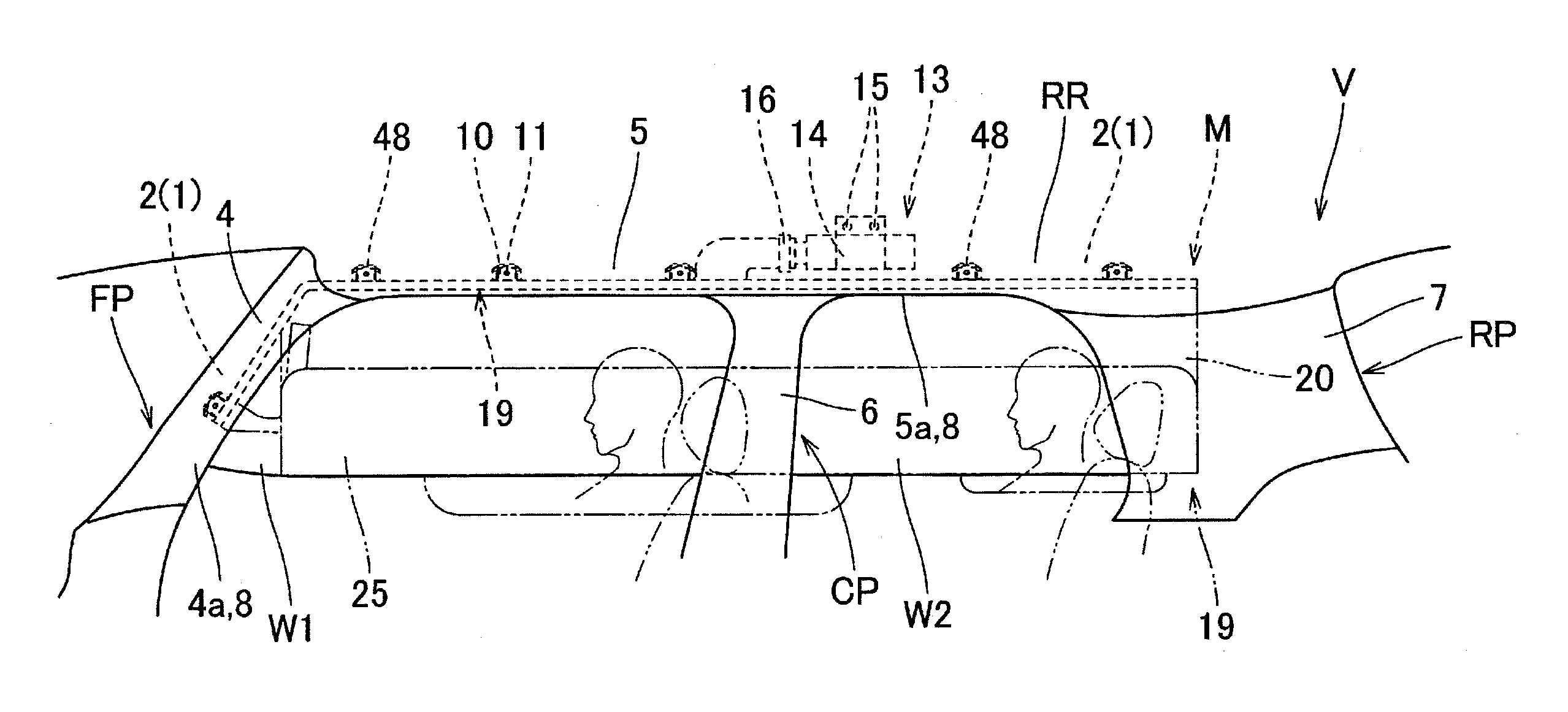
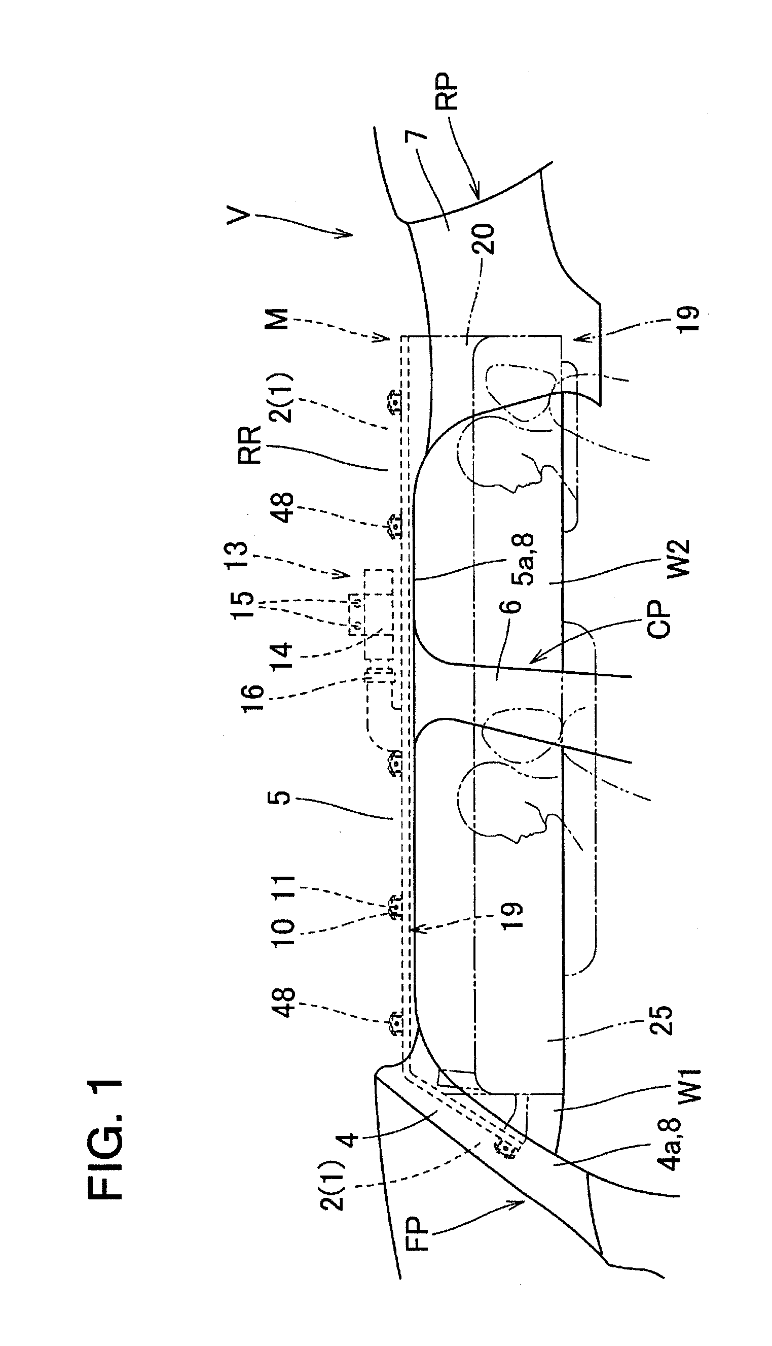
[0027]One embodiment of the present invention will be now described with reference to the accompanying drawings. As shown in FIG. 1, a head protection airbag apparatus M according to the embodiment is mounted in a two-row seat type vehicle V having two windows (side windows) W1 and W2. The head protection airbag apparatus M according to the embodiment includes an airbag 19, an inflator 13, attaching brackets 10 and 14, and an airbag cover 8. The airbag 19, as shown in FIG. 1, is folded and received in upper edges of windows W1 and W2 on the inside of the vehicle V to extend from a lower edge of a front pillar FP to an upper region of a rear pillar RP, via a lower edge of a roof side rail RR.

[0028]As shown in FIG. 1, the airbag cover 8 is constituted of a lower edge 4a of a front pillar garnish 4 arranged on the front pillar FP, and a lower edge 5a of a roof head liner 5 arranged on the roof side rail RR. The front pillar garnish 4 and roof head liner 5, which are made of synthetic r...


PUM


Abstract

A head protection airbag apparatus includes an airbag that is folded and received in an upper edge of a window on an inside of a vehicle, an upper edge of which is attached and fixed to a body of the vehicle, and inflated and protruding downward from a storage region by an inflation gas flowed from an inflator to cover the inside of the window. The air bag includes an inflation shielding section that is arranged to cover the inside of the window upon completion of inflation and an overlap inflation section that is communicated with the inflation shielding section and arranged on an inside or an outside with respect to the vehicle of the inflation shielding section so that an inflation region of the overlap inflation section is overlapped with an inflation region of the inflation shielding section.

Description

CROSS-REFERENCE TO RELATED APPLICATION[0001]This application is based on Japanese Patent Application No. 2013-039157 filed on Feb. 28, 2013, the contents of which are incorporated herein by reference.BACKGROUND OF THE INVENTION[0002]1. Technical Field[0003]The present invention relates to a head protection airbag apparatus, including an airbag adapted to be folded and received in an upper edge of a window on an inside of a vehicle, to be attached and fixed, at an upper edge thereof, to a body of the vehicle, and to inflated to cover the inside of the window while protruding downward from a storage region by an inflation gas flowed from an inflator thereinto.[0004]2. Background Art[0005]Conventionally, as a head protection airbag apparatus, one is known in which, in order to restrain and protect an occupant on an inside of a vehicle even upon a rollover of the vehicle occurred after a side collision thereof, an airbag includes an inflation shielding section inflated to cover the insi...

Claims


Application Information

Patent Timeline
Patent Type & Authority Applications(United States)
IPC IPC(8): B60R21/213
CPCB60R21/213B60R21/233B60R21/23138B60R21/232B60R21/2346B60R2021/161B60R2021/23107B60R2021/23308B60R2021/23316
Inventor KAWAMURA, KOJIMIURA, WATARU
Owner TOYODA GOSEI CO LTD
Why Eureka
Try Eureka