Cartridge and method for filling a consumable into the cartridge

a cartridge and consumable technology, applied in the field of cartridges, can solve the problems of increasing production costs, damage to components, and inability to use cartridges,

Active Publication Date: 2005-01-06
BROTHER KOGYO KK
View PDF7 Cites 30 Cited by
  • Summary
  • Abstract
  • Description
  • Claims
  • Application Information

AI Technical Summary

Benefits of technology

[0011] Accordingly, one exemplary aspect of the invention provides for a cartridge in which a port for filling a consumable is readily formed on the cartridge when the cartridge is reused.
[0015] Another exemplary aspect of the invention is to properly rotate an agitator that agitates a developing agent by supporting a shaft of the agitator accurately.

Problems solved by technology

As the toner filling port is formed using a tool on the top of the cartridge, the tool may contact components such as the agitator provided in the cartridge thus leading to damage to the components.
When the agitator is damaged, the cartridge cannot be used again.
Supporting the shaft of the agitator with bearings protruding from the case also leads to increases in the production costs.

Method used


Image

  • Cartridge and method for filling a consumable into the cartridge
  • Cartridge and method for filling a consumable into the cartridge
  • Cartridge and method for filling a consumable into the cartridge

Examples


first embodiment

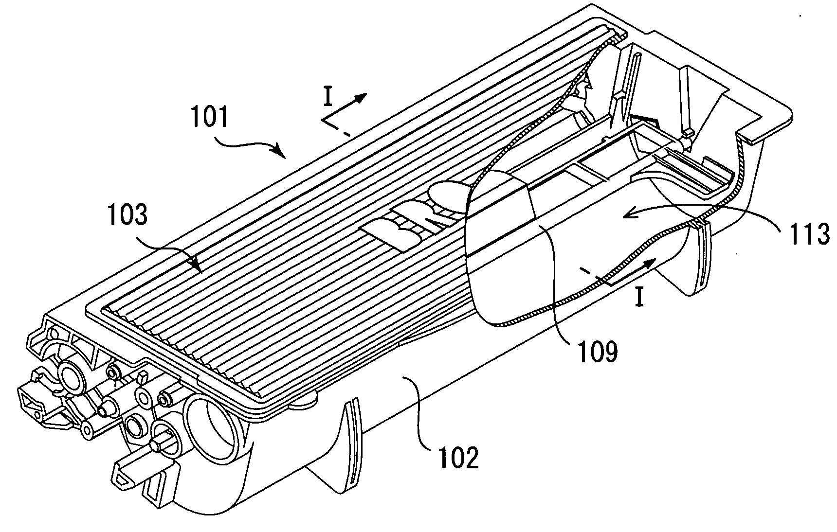
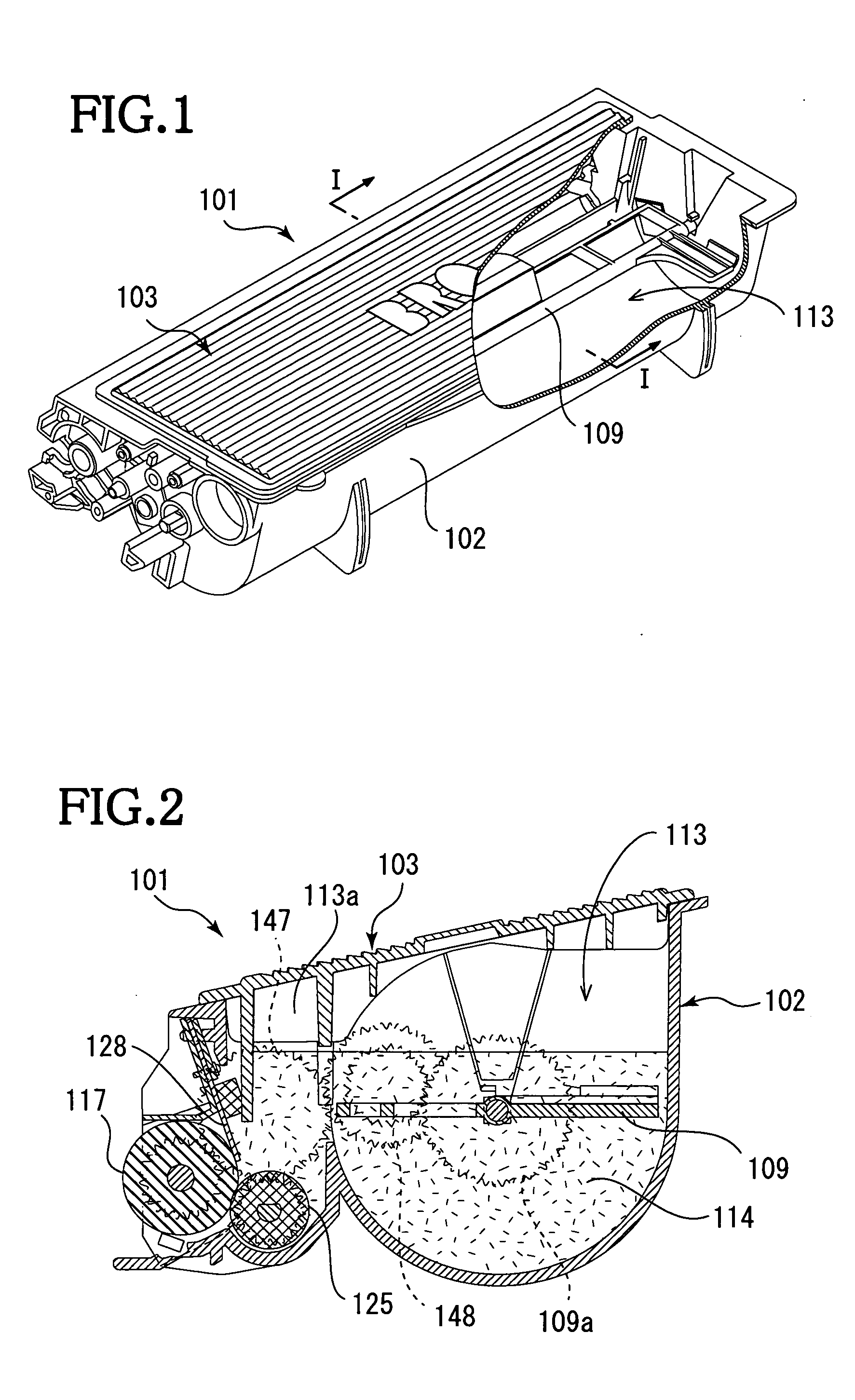
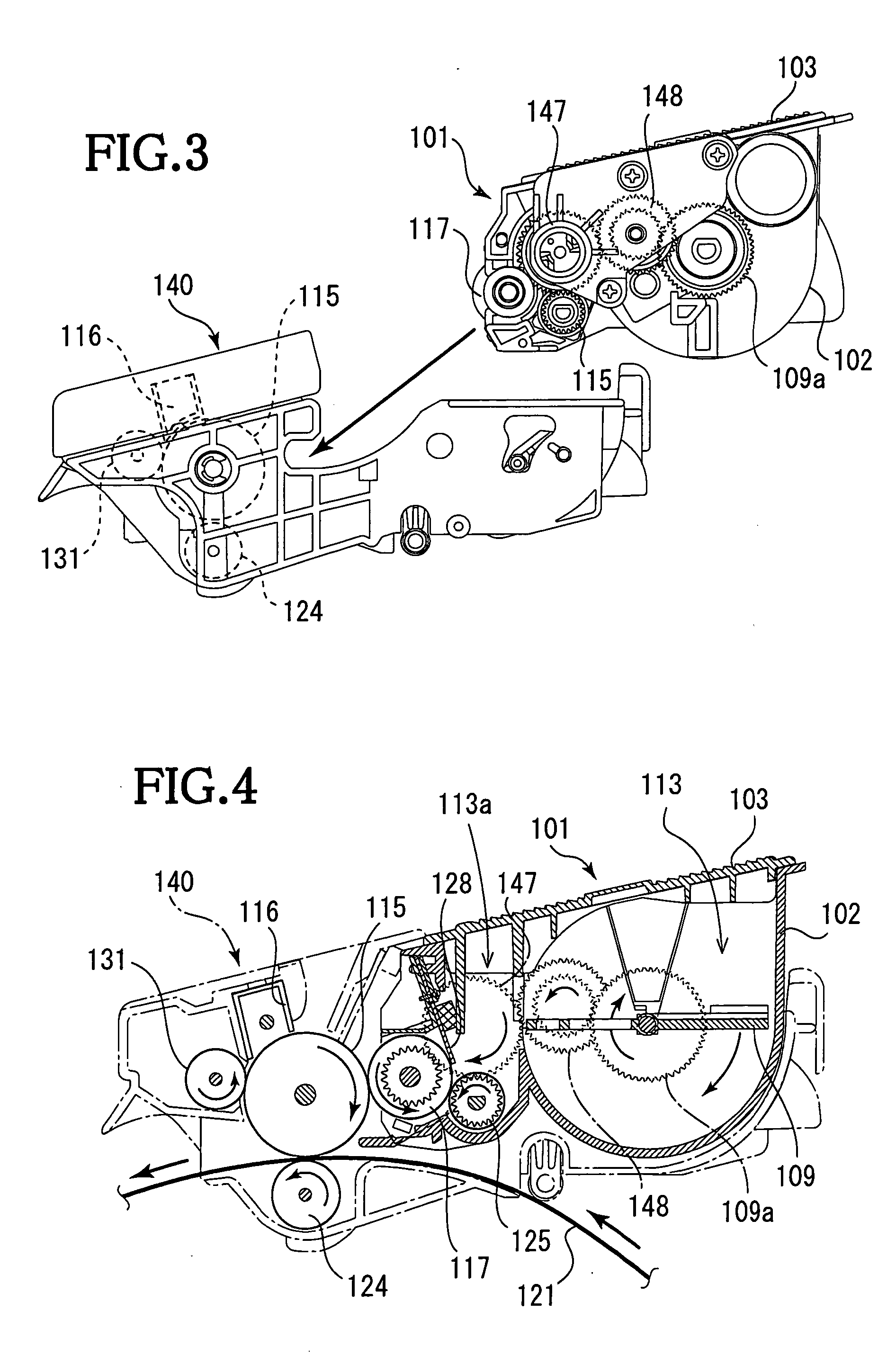
[0044]FIG. 1 shows a replaceable cartridge 101 according to the invention. A case of the cartridge 101 is formed of a plastic material, such as ABS (acrylonitrile butadiene styrene), into a box shape. The cartridge 101 includes a cartridge body 102 of a box shape that is open upwardly and a top 103 that covers the opening of the cartridge body 102. The cartridge body 102 and the top 103 are connected by ultrasonic welding.

[0045] As shown in FIG. 2, provided in an inner space of the cartridge 101 are a toner reservoir 113 and a toner supply portion 113a disposed adjacent to the toner reservoir 113. Toner 114, as a consumable, is filled into the toner reservoir 113 and the toner supply portion 113a.

[0046] Disposed in the toner supply portion 113a are a developing roller 117 that carries thereon the toner 114, a supply roller 125 that supplies the toner 114 to the developing roller 117, and a blade 128 that regulates the thickness of the toner layer carried on a surface of the develop...

second embodiment

[0080] The second embodiment will be described with reference to FIGS. 10A, 10B and 11. As shown in FIG. 10A, the reference plane A defined by the height of the surface of the land area 103a is disposed above the reference plane B defined by the crests 103b′ of the threads 103b. The recess 103d is formed on a reverse side of the land area 103a. The reference plane C defined by the deepest portion 103d′ of the recess 103d is disposed above the reference plane B. The contours of the land area 103a and the recess 103d are similar to each other, but the contour of the recess 103d is smaller than that of the land area 103a.

[0081] When the cartridge 101 is replenished with the toner 114, the surface of the land area 103a is removed, parallel with the top 103 using, for example, a cutter, a file, or a milling machine. As the land area 103a is cut off to the reference plane B, a port 163 is formed at a position associated with the land area 103a, as shown in FIG. 10B. The cartridge 101 is ...

third embodiment

[0085] Referring to FIG. 12, the third embodiment will be described. The top 103 has a flat surface 103j. As the reference plane C is set above the flat surface 103j, a port for replenishing the cartridge 101 with toner 114 is formed by cutting off the land area 103 to the level corresponding to the flat surface 103j, as indicated by the broken line in FIG. 12.


PUM


Abstract

A cartridge includes a case that accommodates a consumable therein, a land area that protrudes from a surface of the case, and a recess that is formed on a reverse side of the surface at a position corresponding to the land area, a reverse side of a deepest portion of the recess being the land area, wherein the deepest portion of the recess is toward the land area with respect to the surface.

Description

CROSS-REFERENCE TO RELATED APPLICATION [0001] This application claims priority from JP 2003-194523, filed Jul. 9, 2003 and JP 2003-189208, filed Jul. 1, 2003, the disclosures of which are incorporated in their entirety herein by reference thereto. BACKGROUND OF THE INVENTION [0002] 1. Field of Invention [0003] The invention relates to a cartridge that is exchangeably mounted on image forming apparatuses, such as printers, facsimile machines, and copiers and that fills thereinto a consumable such as toner and ink. [0004] 2. Description of Related Art [0005] In recent years, a cartridge filled with toner as a developing medium has been used for printers, facsimile machines, and copiers. A certain amount of toner is filled into the cartridge at the time of production. The cartridge is exchangeably set in, for example, a printer. As the toner in the cartridge is used and the remaining amount of the toner is reduced, the printing quality begins to fade. The cartridge thus needs to be rep...

Claims


Application Information

Patent Timeline
Patent Type & Authority Applications(United States)
IPC IPC(8): B41J2/175G03G15/08
CPCG03G15/0894B41J2/17506B41J2/17546G03G21/181G03G21/1857
Inventor SUZUKI, TSUTOMU
Owner BROTHER KOGYO KK
Why Eureka
Try Eureka