Drop-away arrow rest

a drop-away arrow and rest technology, applied in the field of archery, can solve the problems of increasing the weight of the rest, affecting the stability of the arrow, and the adjustment of many arrow supports is severely limited, so as to achieve the effect of simple and efficient, and further vibration dampening

Inactive Publication Date: 2009-10-06
GRACE ENG
View PDF15 Cites 30 Cited by
  • Summary
  • Abstract
  • Description
  • Claims
  • Application Information

AI Technical Summary

Benefits of technology

[0010]In one embodiment, the arrow rest includes an arrow support, a bias member, such as a spring, and a connector, such as a cord, which is connected to a downwardly moving portion of a bowstring of an archery bow. The spring urges the support to a rest position, which is generally out of the way of an arrow being shot from the bow. When the bowstring is drawn, the downwardly moving portion of the bowstring moves down, tensions the connector (working against the bias member) to urge the arrow support to a support position where it properly supports the arrow immediately before the arrow is shot. When the bowstring is released, the downwardly moving bowstring portion removes the tension in the connector, and the bias member rapidly moves the support out of the way of the arrow.
[0015]The drop-away arrow rest of the present invention provides a simple and efficient mechanism to support a ready-to-shoot arrow relative to a bow, and rapidly move a support of the rest out of the way of the arrow as it is shot. Where the arrow rest is optionally constructed from magnesium or magnesium alloy, the rest can provide further vibration dampening for the archery bow to which the rest is mounted.

Problems solved by technology

First, the devices are somewhat complicated and require multiple parts, which can increase the weight of the rests.
Second, the adjustability of many arrow supports is severely limited.
Third, the support arms of many rests simply do not move fast enough out of the path of a shot arrow.

Method used


Image

  • Drop-away arrow rest
  • Drop-away arrow rest
  • Drop-away arrow rest

Examples


first alternative embodiment

III. First Alternative Embodiment

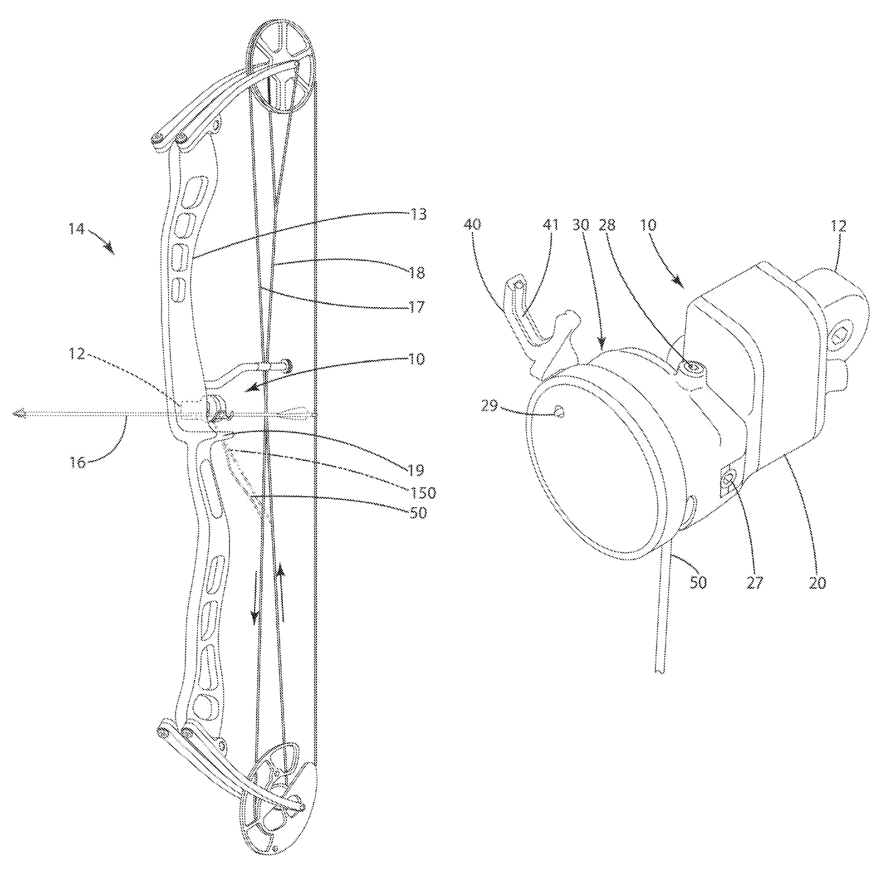
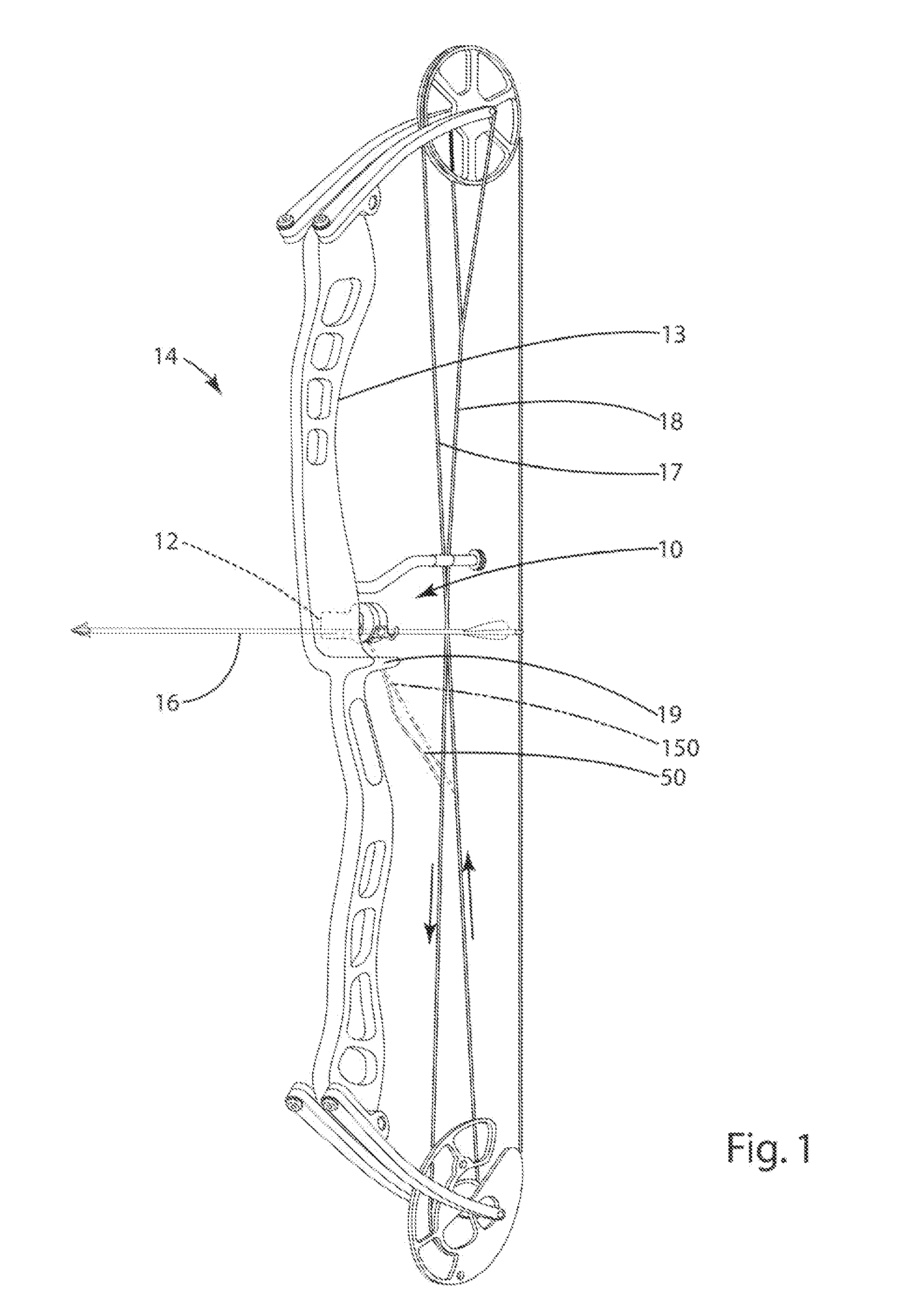
[0052]In another embodiment, the actuation of the arrow support can be modified so that the arrow support movement is actuated by the upwardly moving bowstring portion 18 in FIG. 1. With reference to FIG. 8, this alternative embodiment includes many of the same features of the embodiment described above. The primary difference is the orientation of the connector 150 and bias member 133 relative to the arrow support 400 and the axle 136. As shown, the connector 150 is joined with the arrow support primary arm 144. The bias member 133 exerts an upward force on the arm 140 to urge the arm into or toward engagement with the upward stop 131.

[0053]With reference to FIGS. 1 and 8, the operation of this first alternative embodiment will be described. When the bow 14 is in an undrawn state, the upwardly moving bowstring portion 17 is in its downward most position. The connector 150 is in this embodiment is attached to the upwardly moving bowstring, as shown i...


PUM


Abstract

A drop-away arrow rest including an arrow support that rotates in a vertical plane about a horizontal axis parallel to of a supported arrow. The rest can include a bias member and a connector joined with an upward moving bowstring portion and / or a downward moving bowstring portion. The bias member urges the support to a support position and / or a rest position. Movement of a bowstring portion correspondingly moves the connector so that the connector moves the support about an axis that is substantially parallel to a supported arrow, thereby moving the support to at least one of a support position and a rest position. Optionally, an indicator indicates when the support is in the support position. Further optionally, the connector can be secured to a connector device defining an aperture and joined with a bowstring portion.

Description

[0001]This application claims benefit of U.S. provisional patent application 60 / 784,940, filed Mar. 23, 2006, which is hereby incorporated by reference.BACKGROUND OF THE INVENTION[0002]The present invention relates to an archery drop-away arrow rest and a related method of manufacture.[0003]Most archery bows include an arrow rest that holds an arrow before it is shot from the bow. An increasingly common arrow rest is referred to as a “drop-away” arrow rest. This rest precisely and accurately positions the arrow when the bow (and thus, the bowstring) is at full draw, but drops rapidly forward and away from the arrow upon release of the bowstring. Accordingly, the rest does not to contact the arrow or the arrow's fletching and divert the arrow from its intended trajectory as the arrow is shot from the bow.[0004]A variety of drop-away arrow rests exist. The common elements of such rests are: (a) an arrow support that holds the arrow shaft in a loaded position at full draw and subsequen...

Claims


Application Information

Patent Timeline
Patent Type & Authority Patents(United States)
IPC IPC(8): F41B5/22
CPCF41B5/143
Inventor GRACE, JR., LOUISGRACE, NATHANIEL E.
Owner GRACE ENG
Why Eureka
Try Eureka