Infusion pump
a technology of infusion pump and pump body, which is applied in the direction of positive displacement liquid engine, process and machine control, instruments, etc., can solve the problems of reducing the rate of infusion per unit time, and it is not possible to completely eliminate the reduction so as to suppress the reduction of the accuracy of the rate of infusion
- Summary
- Abstract
- Description
- Claims
- Application Information
AI Technical Summary
Benefits of technology
Problems solved by technology
Method used
Image
Examples
embodiment 1
[0051]Referring to FIGS. 1-10, an infusion pump according to the present invention will be described.
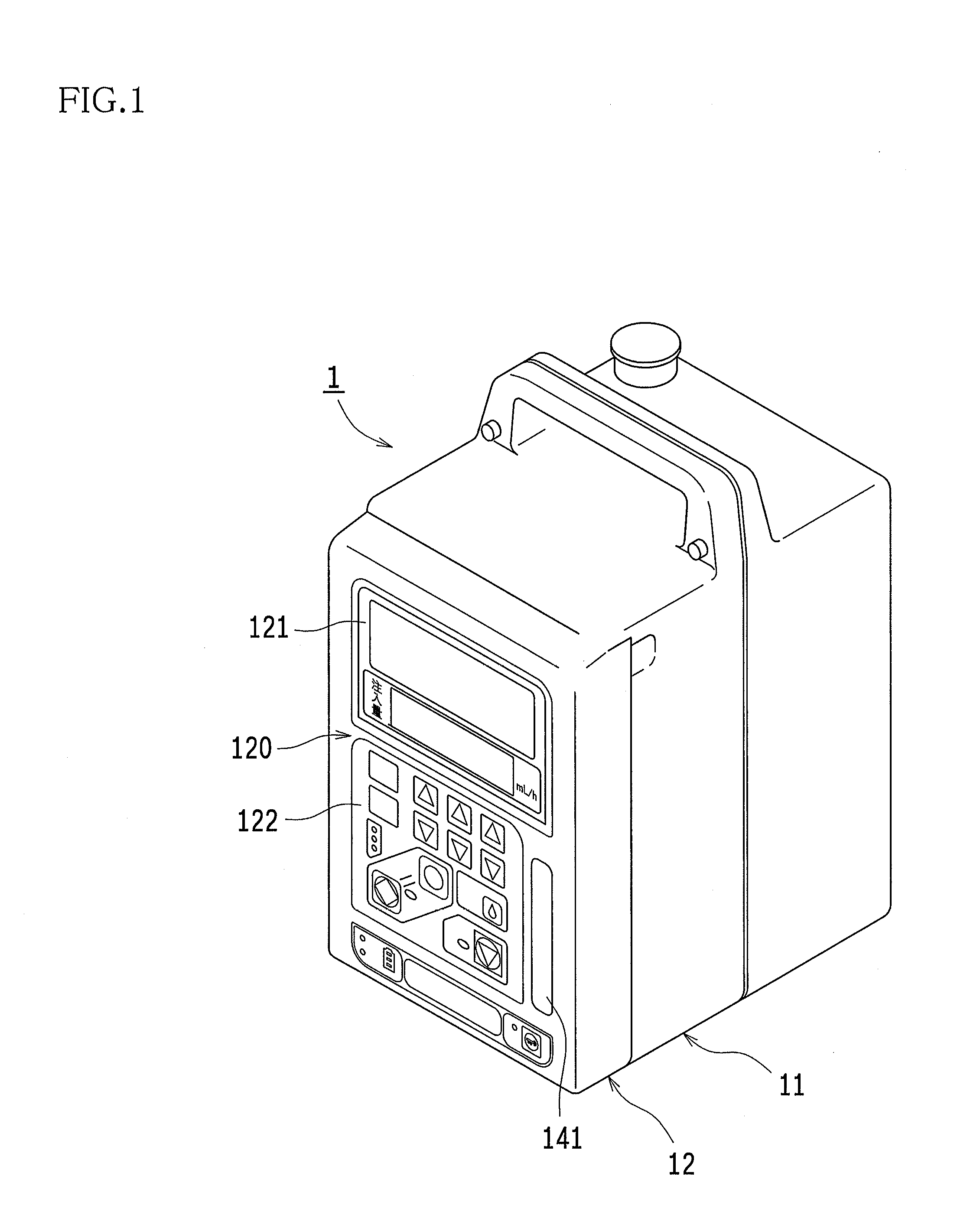
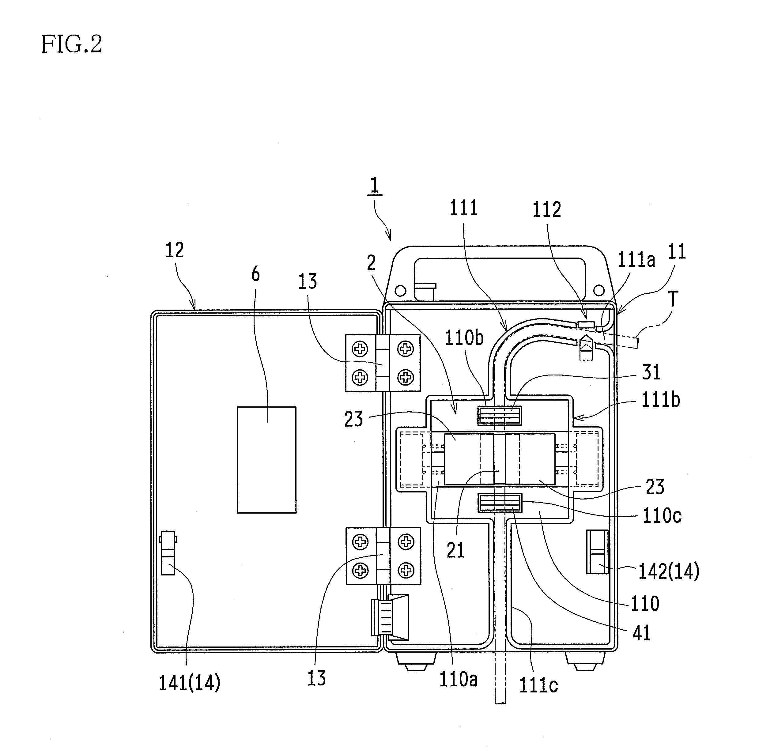
[0052]An infusion pump 1 in this embodiment, which is a half-occlusion type infusion pump, comprises a pump body (casing) 11 and a door 12 which closes a front side (at a tube mounting position) of the pump body 11. The door 12 is swingably (turnably) supported on the pump body 11 by hinges 13, 13 and is adapted to be able to swing from a position to fully close the front side of the pump body 11 to its full open position (for example, a position where the door is opened at 180 degrees).
[0053]The pump body 11 and the door 12 have a door lock mechanism 14 to hold the closed state when the door 12 is closed. The door lock mechanism 14 comprises a door lock lever 141, a hook 142 and the like, and therefore the door 12 can be locked by pivoting the door lock lever 141 when the door 12 is closed and then engaging the door lock lever 141 with the hook 142.
[0054]The pump body 11 also has a ...
embodiment 2
[0108]Referring to the FIGS. 12-14, another example of the infusion pump according to the present invention will be described.
[0109]In the infusion pump in this example, the configuration other than a tube pressing section 220 (pump mechanism) described below is essentially same as that of the above [Embodiment 1], and accordingly will not be described in detail.
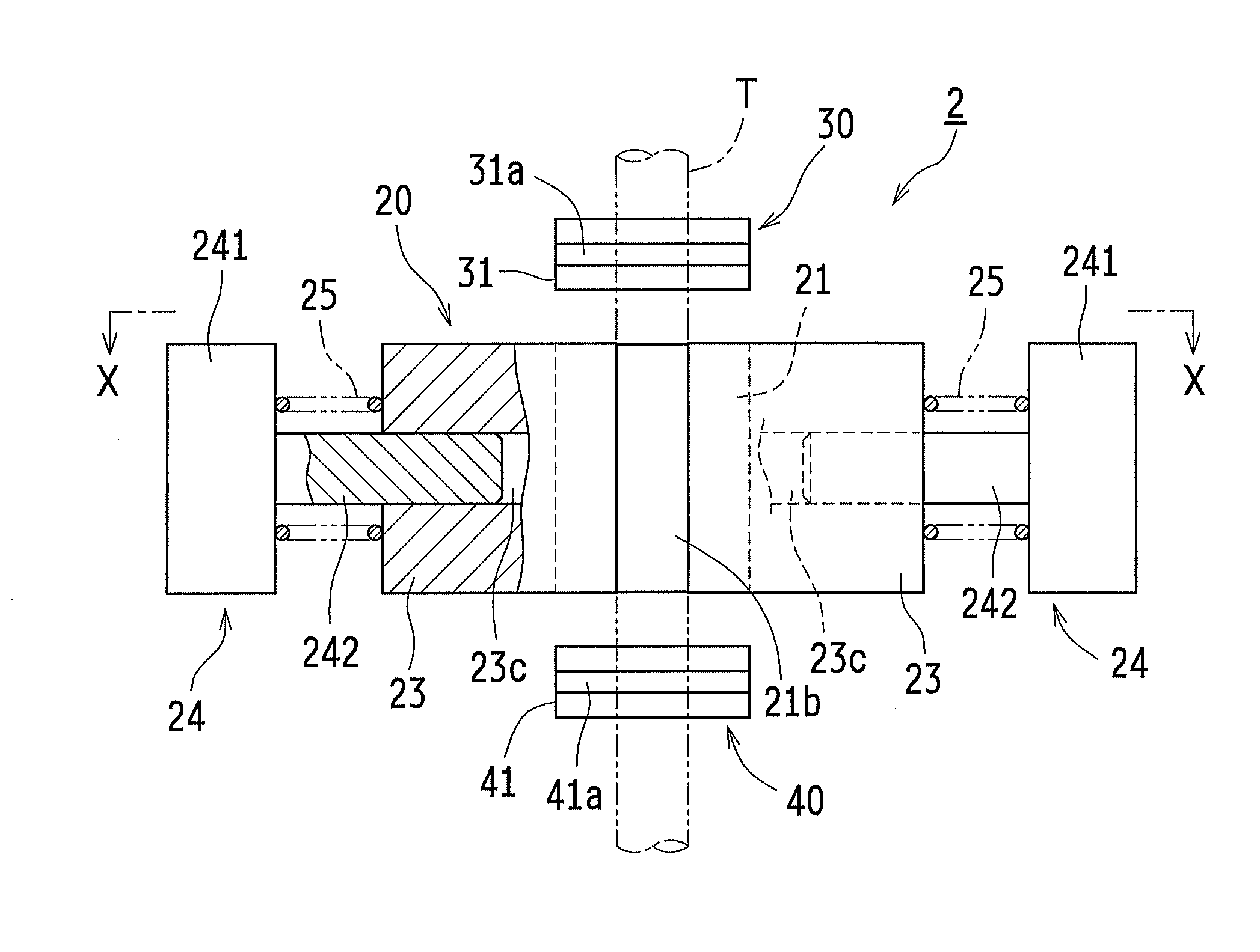
[0110]The tube pressing section 220 comprises a primary finger 221, an actuator 222, a secondary finger 223, a fixed finger 230, a sliding support member 240, a compression coil spring 225 etc. and the technical feature of the tube pressing section 220 is in that a single secondary finger 223 is provided for a single primary finger 221.
[0111]The primary finger 221 is a member with a rectangular cross section and has an inclined surface 221a provided on one side surface thereof. The inclined surface 221a is inclined to an advancing and retracting direction of the primary finger 221 (a direction along the central axis CL1). An...
embodiment 3
[0136]The still other example of the infusion pump according to the present invention will be described with reference to FIGS. 15-23. Note that, in FIGS. 17 and 19-21, an eccentric cam 322a is illustrated without being cut away.
[0137]An infusion pump 300 in this example comprises the pump body 11 and the door 12 which closes the front side (at the tube mounting position) of the pump body 11. The door 12 is swingably (turnably) supported on the pump body 11 by the hinges 13, 13 and is adapted to be able to swing from the position to fully close the front side of the pump body 11 to its full open position (for example, the position in which the door is opened at 180 degrees).
[0138]In the infusion pump 300 in this example, the configuration other than those described below is essentially same as that of the above [Embodiment 1], and accordingly will not be described in detail.
[0139]The infusion pump 300 in this example, which is of a peristaltic finger type (the full-press), comprises...
PUM
 Abstract
Description
Claims
Application Information
 - R&D
- Intellectual Property
- Life Sciences
- Materials
- Tech Scout
- Unparalleled Data Quality
- Higher Quality Content
- 60% Fewer Hallucinations
Browse by: Latest US Patents, China's latest patents, Technical Efficacy Thesaurus, Application Domain, Technology Topic, Popular Technical Reports.
© 2025 PatSnap. All rights reserved.Legal|Privacy policy|Modern Slavery Act Transparency Statement|Sitemap|About US| Contact US: help@patsnap.com


