Neurostimulation system having increased flexibility for creating complex pulse trains

a neurostimulation system and pulse train technology, applied in the field of tissue stimulation systems, can solve the problems of limiting the capacity of current neuromodulation systems, unable to accommodate pulse trains, and presently existing neuromodulation hardware may be a monumental task, so as to facilitate temporal integration of pulses

Active Publication Date: 2014-08-28
BOSTON SCI NEUROMODULATION CORP
View PDF1 Cites 44 Cited by
  • Summary
  • Abstract
  • Description
  • Claims
  • Application Information

AI Technical Summary

Benefits of technology

This patent describes a brain stimulation device called a neuromodulation system that can produce specific patterns of electricity on certain parts of the body's nervous system. These patterns are controlled through software programming, allowing researchers to study how different types of neural activity affect behavior and cognition. One key feature of this system is its ability to combine multiple sequences of electricity into a single waveform, resulting in a higher overall level of power compared to traditional methods. Another advantage is its flexibility: users can choose their own pattern of pulses and even select specific locations where they want them applied. Overall, this technology provides a powerful tool for studying the complexities of human physiology and could potentially lead to new treatments for medical conditions like epilepsy or depression.

Problems solved by technology

The technical problem addressed in this patent text is how to enable better flexibility in selecting optimal settings for neurology procedures utilizing neuromodulation devices. Current systems use preset programming options but cannot always produce ideal results due to variations in factors like disease state or individual needs. Additionally, while high-frequency modulation offers greater effectiveness than traditional methods, designing new hardware to implement these techniques could take significant effort. There is also a need for easier ways to update existing systems to generate more complex pulse trains.

Method used


Image

  • Neurostimulation system having increased flexibility for creating complex pulse trains
  • Neurostimulation system having increased flexibility for creating complex pulse trains
  • Neurostimulation system having increased flexibility for creating complex pulse trains

Examples


Embodiment Construction

[0036]The description that follows relates to a spinal cord modulation (SCM) system. However, it is to be understood that while the invention lends itself well to applications in spinal cord modulation, the invention, in its broadest aspects, may not be so limited. Rather, the invention may be used with any type of implantable electrical circuitry used to stimulate tissue. For example, the present invention may be used as part of a pacemaker, a defibrillator, a cochlear stimulator, a retinal stimulator, a stimulator configured to produce coordinated limb movement, a cortical stimulator, a deep brain stimulator, peripheral nerve stimulator, microstimulator, or in any other neurostimulator configured to treat urinary incontinence, sleep apnea, shoulder sublaxation, headache, etc.

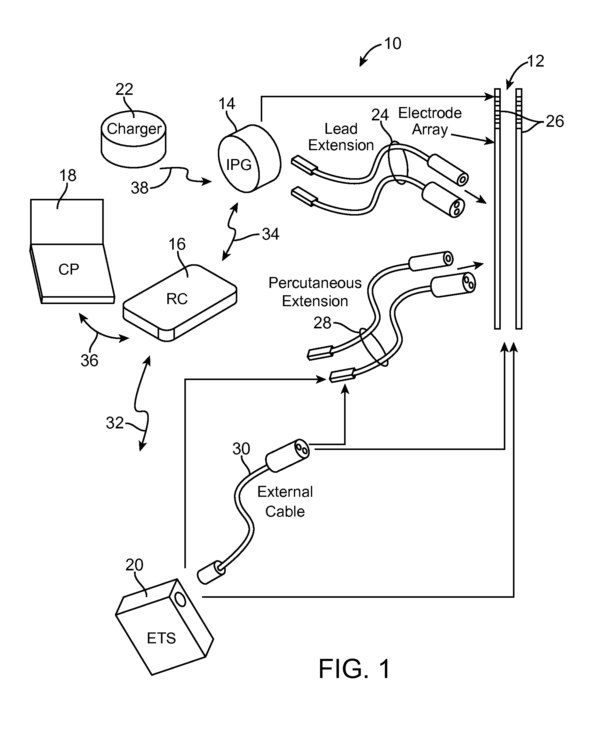
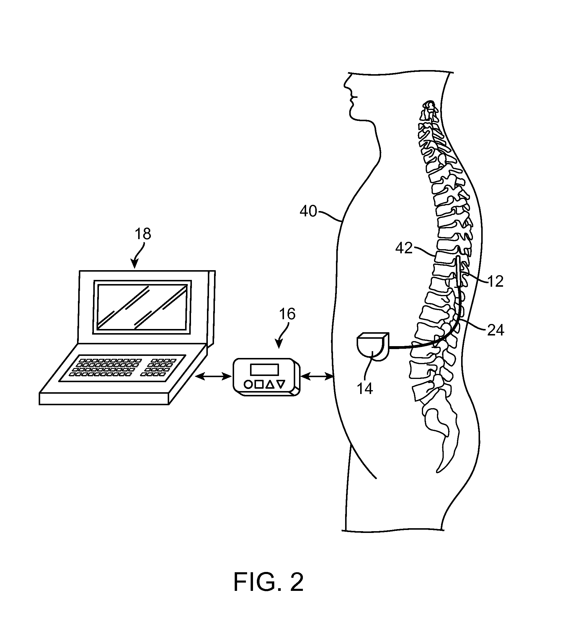
[0037]Turning first to FIG. 1, an exemplary SCM neuromodulation system 10 generally includes one or more (in this case, two) implantable modulation leads 12, an implantable pulse generator (IPG) 14, an externa...


PUM


Abstract

A neuromodulation system comprises electrical terminals configured for being respectively coupled to electrodes. The system further comprises modulation output circuitry configured for respectively outputting individual electrical pulse trains in timing channels to the electrical terminals, wherein each of the pulse trains has a modulation pulse, and at least one of the pulse trains has a charge recovery pulse associated with the modulation pulse of the respective pulse train. The neuromodulation system further comprises control circuitry configured for controlling the modulation output circuitry in a manner that sequentially outputs the modulation pulses of the respective pulse trains to a common set of the electrical terminals without an intervening charge recovery pulse, and outputting the charge recovery pulse(s) to the common set of the electrical terminals subsequent to the sequential modulation pulses, thereby creating a combined electrical pulse train at the common set of electrical terminals.

Description


Claims


Application Information

Patent Timeline
Owner BOSTON SCI NEUROMODULATION CORP
Why Eureka
Try Eureka