Deflection mechanism

a technology of deflection mechanism and steering mechanism, which is applied in the field of deflection mechanism, can solve the problems of known steering mechanism may present certain drawbacks for users, and difficult introduction of force leverag

Active Publication Date: 2014-09-11
BOSTON SCI SCIMED INC
View PDF14 Cites 132 Cited by
  • Summary
  • Abstract
  • Description
  • Claims
  • Application Information

AI Technical Summary

Benefits of technology

[0009]The present disclosure is further drawn to a steering mechanism for use in a medical device, comprising: a first lever rotatable about a first axis, the first lever coupled to a first cam and configured to move the first cam from a first position to a second position when rotated about the first axis to provide a first deflection of a distal end of the medical device; a second lever rotatable about a second axis, the second lever coupled to a second cam and configured to move the second cam from a first position to a second position when rotated about the second axis to provide a second deflection of the distal end of the medical device, and an object connecting the first lever to the second lever, wherein the first lever and the second lever are configured to move independently or concertedly by moving the object. In some embodiments, the object includes a button slidable within a first closed slot in the first lever and a second closed slot in the second lever. In some embodiments, sliding the button within the first closed slot and the second closed slot simultaneously allows for deflection of the distal end of the medical device along more than two planes.

Problems solved by technology

Known steering mechanisms may present certain drawbacks for users.
Additionally, the single control element encompassed in the joystick control mechanism makes the introduction of force leverage difficult, especially in a procedure during which an increased leverage is needed for different articulation planes.
The sliding motion of the buttons on this steering mechanism makes introduction of force leverage very difficult.

Method used


Image

  • Deflection mechanism
  • Deflection mechanism
  • Deflection mechanism

Examples


Embodiment Construction

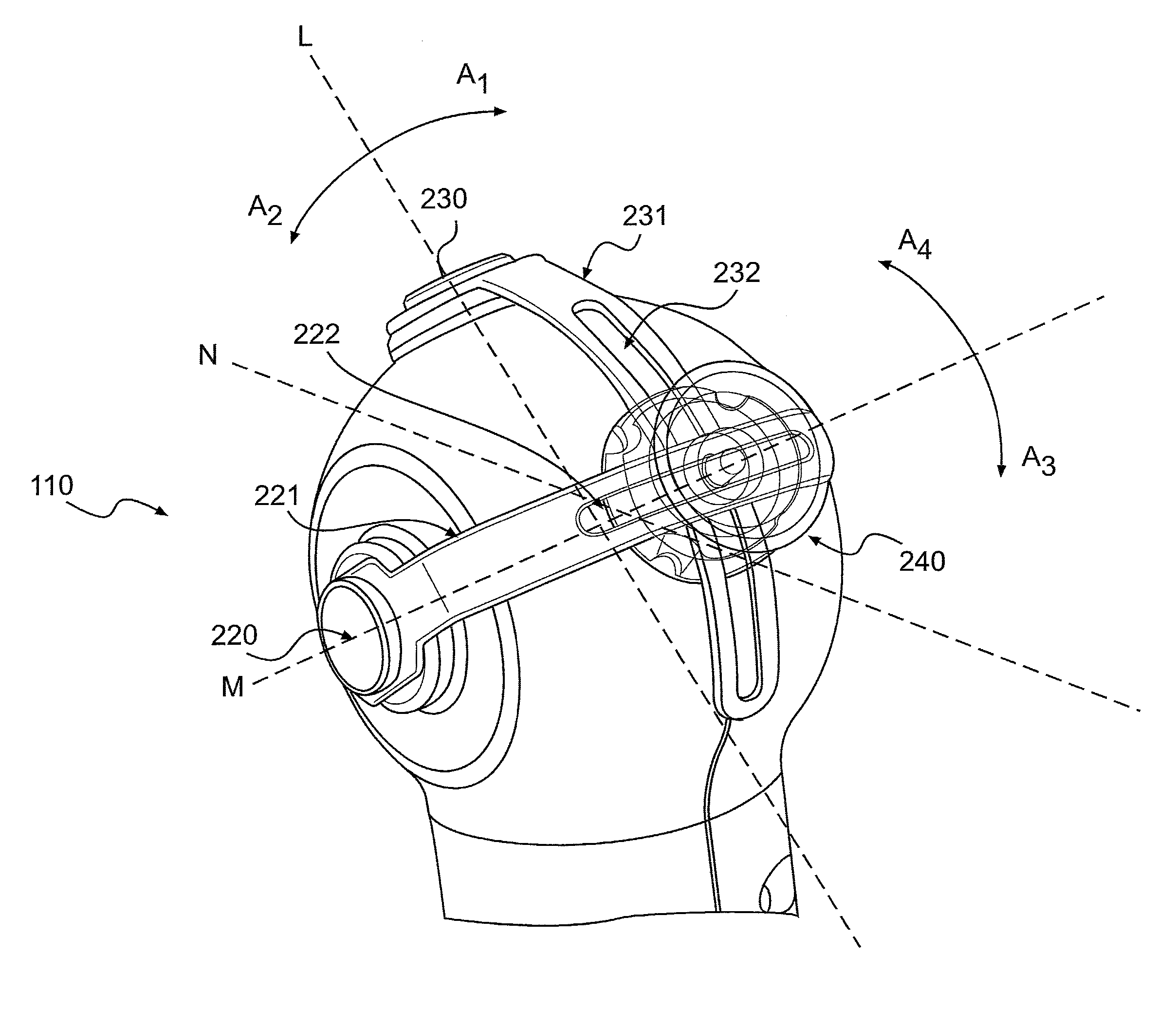
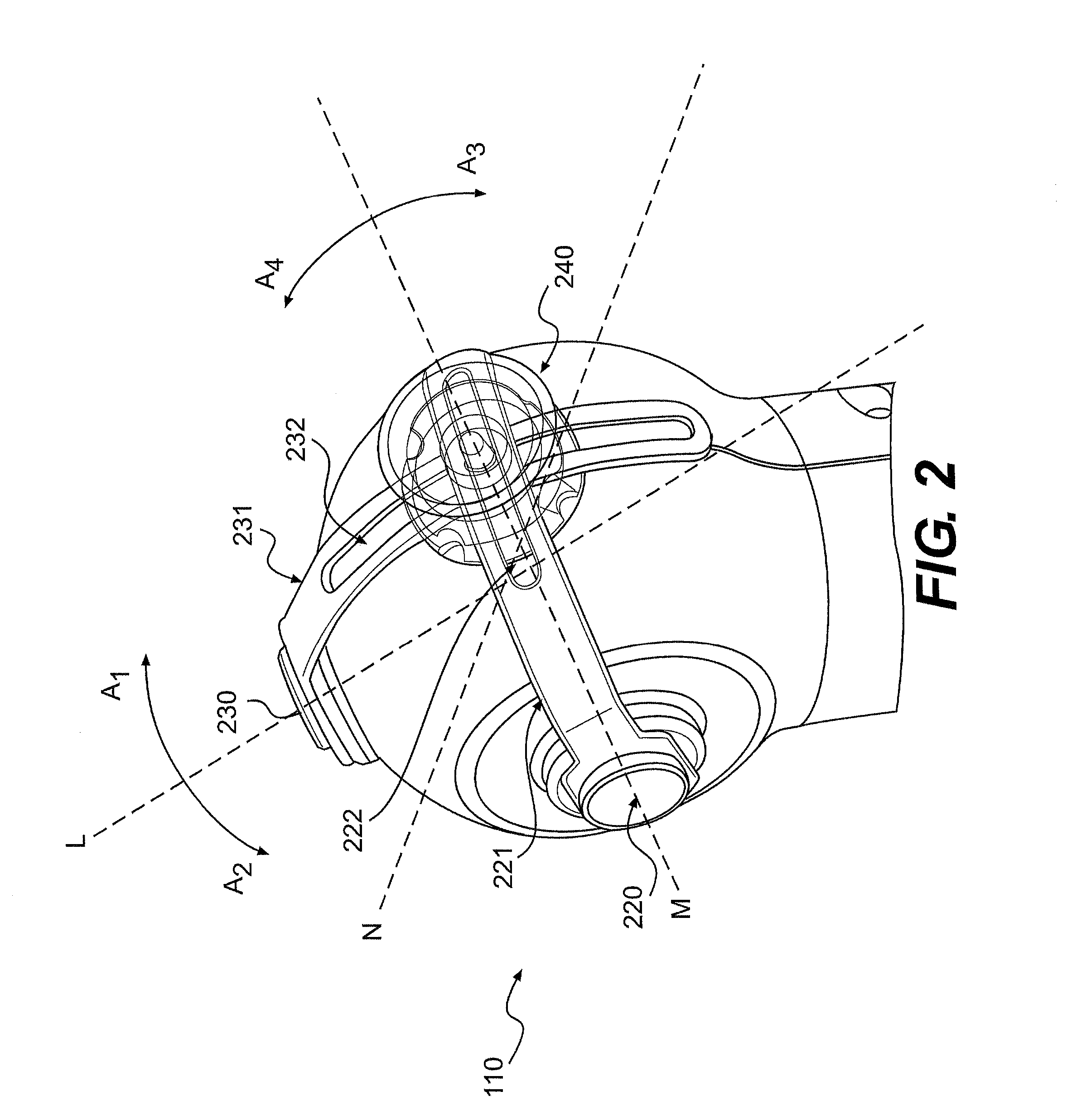
[0015]Devices for controlled articulation of a steerable member are described herein. In some embodiments, for example, the device may comprise a steering mechanism. The steering mechanism can be used as part of, or in conjunction with, a medical device including a steerable member, such as, for example, a catheter or endoscope. The steerable member may be useful in various medical procedures, such as navigating pathways in a body of a patient.

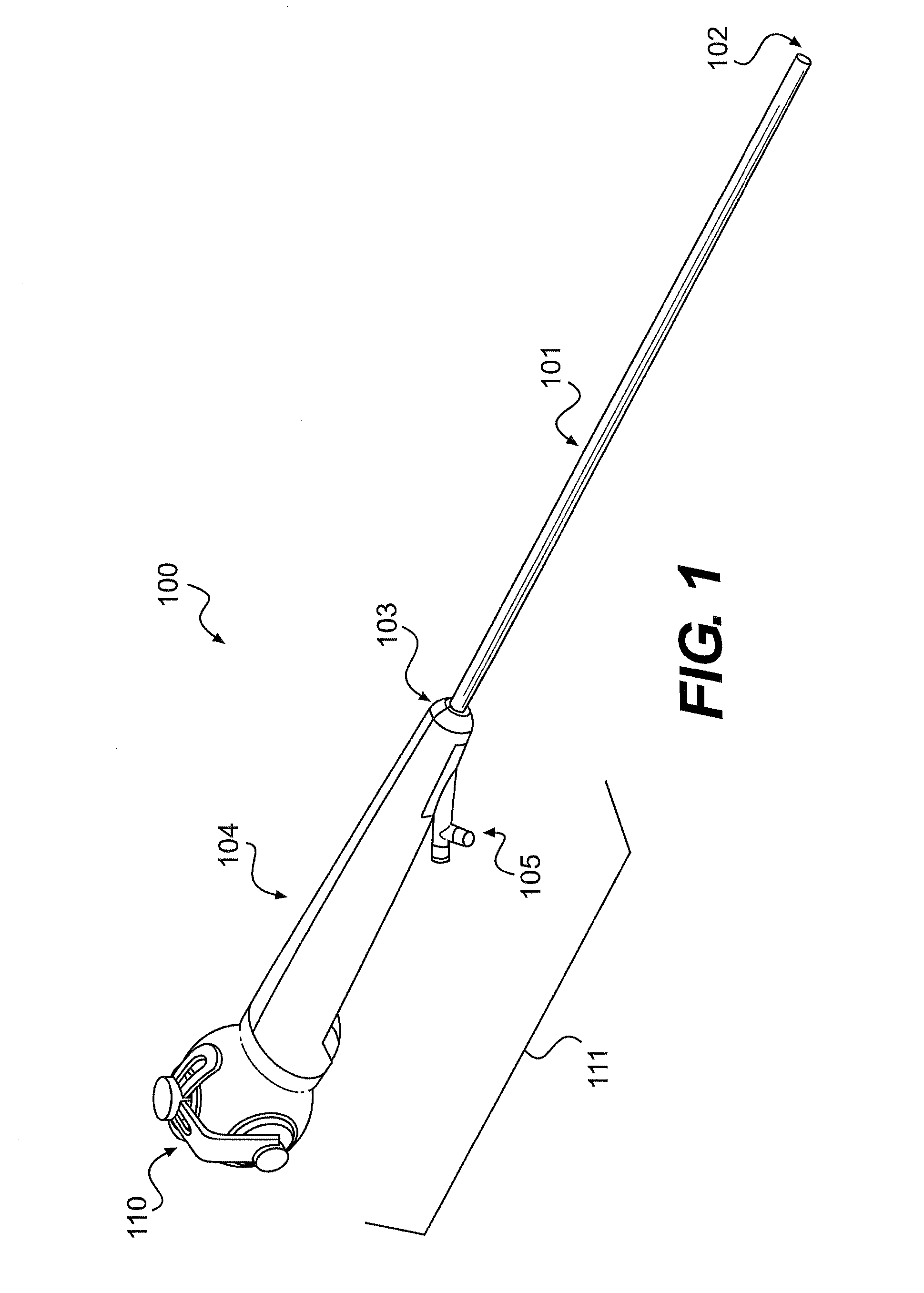
[0016]In one embodiment of the present disclosure, schematically illustrated in FIG. 1, the device 100 may comprise steering mechanism 111 and elongate member 101. The steering mechanism includes an actuation system 110 and a housing 104 equipped with one or more ports 105. The elongate member 101 includes a proximate end 103 and a distal end 102. In some embodiments, the actuation system 110 is adapted to control articulation of the distal end 102 of the elongate member 101 along a first plane and a second plane different than the first plane...


PUM


Abstract

A steering mechanism may comprise an actuation system for one-fingered operation by a user, the system configured to move at least a distal portion of the medical device such that 360 degree articulation is achievable, and a housing coupled to the system, the housing having proximal and distal ends. The system may comprise a first lever rotatable about a first axis, the first lever coupled to a first cam and configured to move the first cam from a first position to a second position when rotated about the first axis to deflect the distal portion; and a second lever rotatable about a second axis, the second lever coupled to a second cam and configured to move the second cam from a first position to a second position when rotated about the second axis to deflect the distal portion, wherein the first lever is coupled to the second lever.

Description

CROSS-REFERENCE TO RELATED APPLICATION[0001]This application claims the benefit of U.S. Provisional Application No. 61 / 776,152, filed Mar. 11, 2013, the disclosure of which is incorporated herein by reference in its entirety.TECHNICAL FIELD[0002]The present disclosure generally relates to a mechanism for controlling articulation of a steerable portion of a medical device.BACKGROUND[0003]Steering mechanisms are used to steer or direct a medical instrument, for example a catheter or endoscope, to a desired position or location in a body of a patient. Known steering mechanisms may present certain drawbacks for users. One known steering mechanism, for example, resembles a joystick. The configuration of the joystick usually includes a plate attached to control wires. The plate, however, must be large to accommodate the desired articulations of the steerable medical device. Additionally, the single control element encompassed in the joystick control mechanism makes the introduction of for...

Claims


Application Information

Patent Timeline
Patent Type & Authority Applications(United States)
IPC IPC(8): F16H21/40
CPCF16H21/40A61B1/0052A61M25/0136A61M25/0147A61B2017/003A61B1/0057Y10T74/18568
Inventor ASSELIN, WILLIAMBARENBOYM, MICHAEL
Owner BOSTON SCI SCIMED INC
Why Eureka
Try Eureka