Display device

Active Publication Date: 2014-09-11
SEIKO EPSON CORP
View PDF3 Cites 51 Cited by
  • Summary
  • Abstract
  • Description
  • Claims
  • Application Information

AI Technical Summary

Benefits of technology

[0008]An advantage of some aspects of the invention is to provide a d

Problems solved by technology

However, in the imaging element of Patent Document 1, there has been a problem of cost rise in rotation and arrangement of the unit optical elements in an arbitrary direction because the design and the manufacture of the imaging element become extremely complex.
Furt

Method used


Image

  • Display device
  • Display device
  • Display device

Examples


first embodiment

[0047]As below, the first embodiment of the invention will be explained using FIGS. 1 to 14.

[0048]A display device of the embodiment is an example of a display device that may generate a planar image in a space.

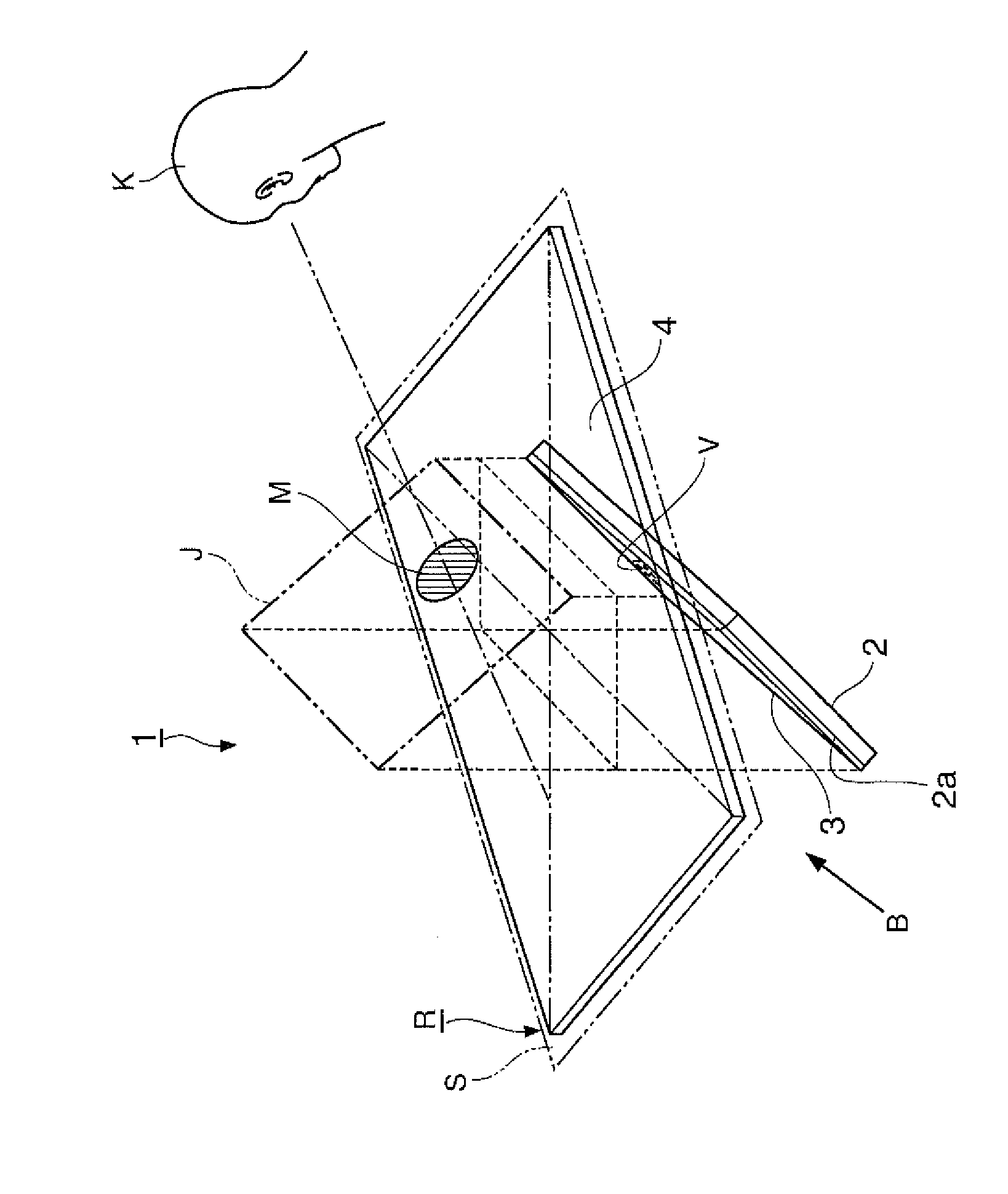
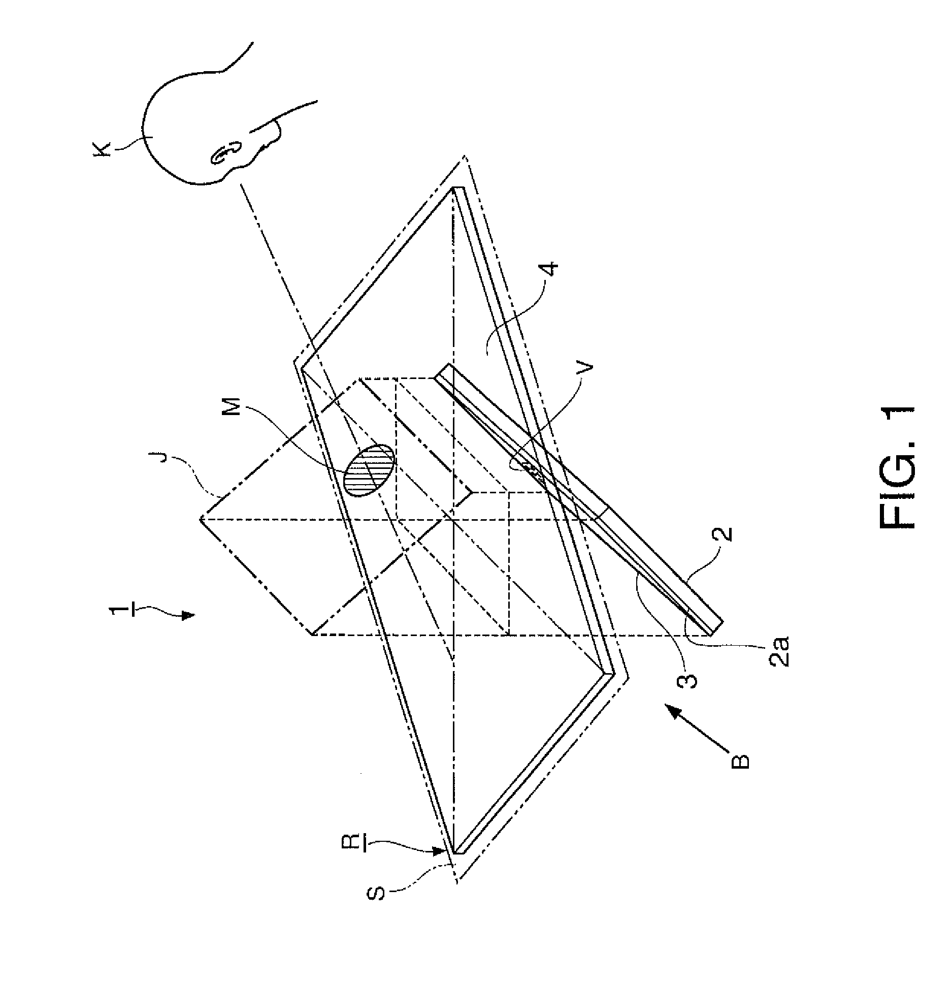
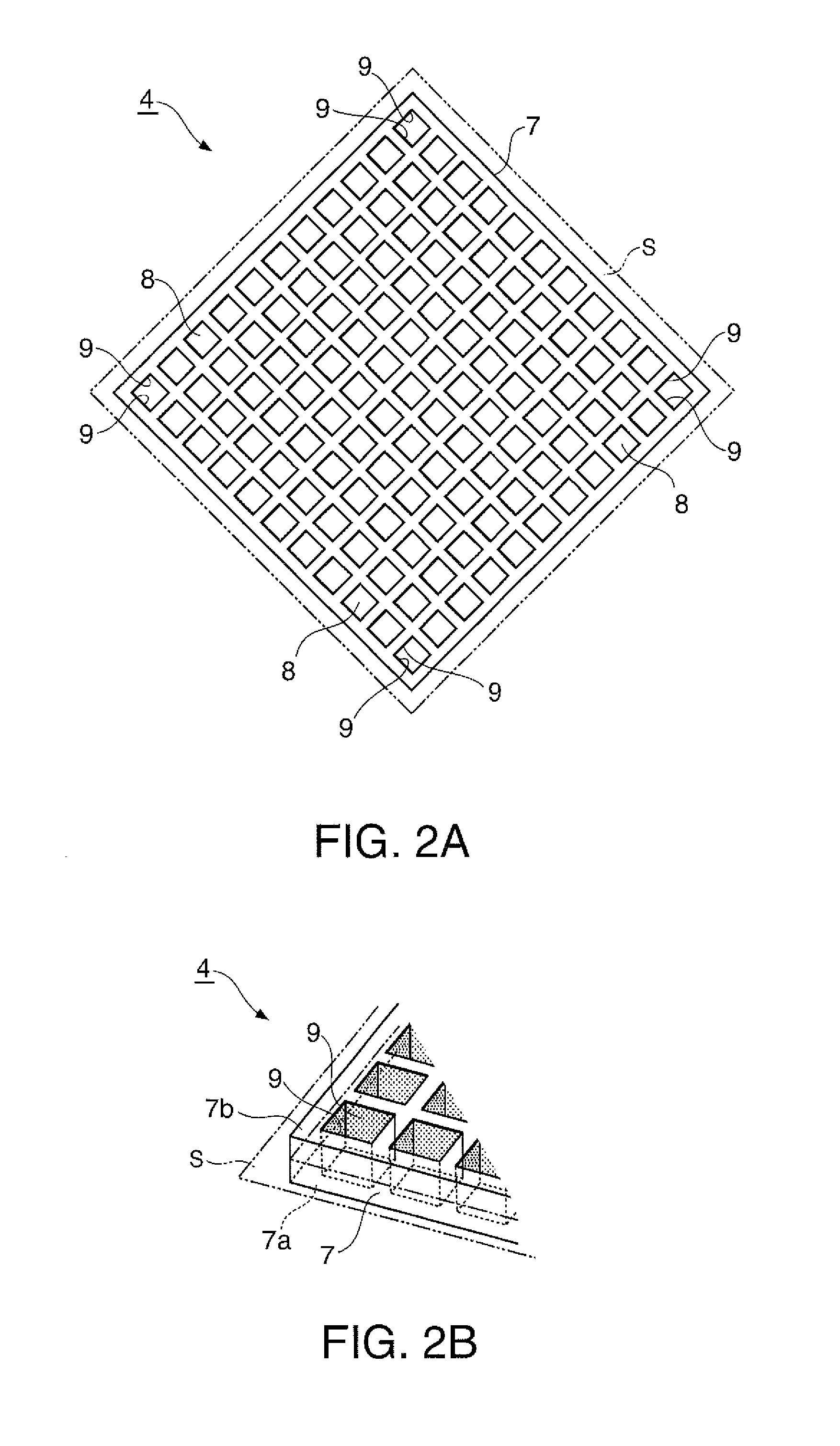
[0049]FIG. 1 is a perspective view showing a schematic configuration of the display device of the embodiment.

[0050]Note that, in all of the following drawings, the scale of dimensions may be made different depending on component elements for facilitating visualization of the respective component elements.

[0051]As shown in FIG. 1, the display device 1 of the embodiment includes a flat panel display 2 (object image generator), a diffusion angle limiting film 3 (diffusion angle limiting member), and a retrotransmissive material 4 (imaging element). In the following explanation, the flat panel display 2 will be abbreviated to FPD. The FPD 2 displays characters and images on an image display surface 2a (image generation surface) based on image signals input from the outside. In th...

second embodiment

[0096]The second embodiment of the invention will be explained using FIGS. 15 and 16.

[0097]The basic configuration of a display device of the embodiment is the same as that of the first embodiment, and the configuration of the object image generator is different from that of the first embodiment.

[0098]FIG. 15 is a perspective view showing a schematic configuration of the display device of the embodiment. FIG. 16 is a sectional view of a screen and a diffusion angle limiting film used for the display device of the embodiment.

[0099]In FIGS. 15 and 16, the common component elements to those in the drawings of the first embodiment have the same signs and their explanation will be omitted.

[0100]As shown in FIG. 15, the display device 21 of the embodiment includes a projection system 22 (object image generator), the diffusion angle limiting film 3 (diffusion angle limiting member), and the retrotransmissive material 4 (imaging element). The projection system 22 includes a transmissive scr...

third embodiment

[0103]As below, the third embodiment of the invention will be explained using FIGS. 17 to 19.

[0104]A display device of the embodiment is the same as the second embodiment in that the object image generator includes the screen and the projector, and different from the second embodiment in the configuration of the diffusion angle limiting member.

[0105]FIG. 17 is a perspective view showing a schematic configuration of the display device of the embodiment. FIG. 18 is a sectional view of a screen assembly used for the display device of the embodiment.

[0106]In FIGS. 17 and 18, the common component elements to those in the drawings of the second embodiment have the same signs and their explanation will be omitted.

[0107]As shown in FIG. 17, the display device 31 of the embodiment includes a projection system 32 (object image generator) and the retrotransmissive material 4 (imaging element). The projection system 32 includes a screen assembly 33 and a projector 34 that projects an image on t...


PUM


Abstract

A display device includes a flat panel display (object image generator) that generates an object image, a retrotransmissive material (imaging element) that has an element surface tilted with respect to an image generation surface of the object image generator, reflects light emitted from the object image located at one side of the element surface twice, and forms the object image as a real image in a plane-symmetrical location with the element surface in a space at the other side of the element surface, and a diffusion angle limiting film (diffusion angle limiting member) that limits a diffusion angle of light from the object image generator toward the imaging element within a predetermined angle range.

Description

BACKGROUND[0001]1. Technical Field[0002]The present invention relates to a display device.[0003]2. Related Art[0004]A display device including an imaging element that forms an image of a projected object and generates a real image in the air using the imaging element has been disclosed in Patent Document 1 (International Publication No. 2007 / 116639).[0005]The imaging element used for the display device disclosed in Patent Document 1 includes unit optical elements each including a dihedral corner reflector having two orthogonal mirror surfaces. The imaging element has a function of generating a real image of a projected object placed in a space at one side of the element surface in a plane-symmetrical location with the element surface in a space at the other side of the element surface. Accordingly, when a solid object is placed in the space at the one side of the element surface, a stereoscopic image is generated in the plane-symmetrical location with the element surface in the spac...

Claims


Application Information

Patent Timeline
IPC IPC(8): G03B21/28G02B30/27
CPCG03B21/28G03B21/10G03B21/625G03B35/24G02B2207/123H04N13/39H04N13/388G02B30/56G02B30/27G02B27/10G02B5/136H04N5/72
Inventor YONENO, KUNIO
Owner SEIKO EPSON CORP
Why Eureka
Try Eureka