Holding device for an intraoral scanner

a scanner and holding device technology, applied in boring tools, dental tools, dental prosthetics, etc., can solve the problems of inability to carry a large amount of equipment, etc., to achieve the effect of easy hanging or placing

Inactive Publication Date: 2014-09-11
A TRON3D
View PDF13 Cites 9 Cited by
  • Summary
  • Abstract
  • Description
  • Claims
  • Application Information

AI Technical Summary

Benefits of technology

[0005]Thus, the intraoral scanner with its head area can be hung or placed easily and quickly in the holding device.

Problems solved by technology

The space requirement that is frequently substantial is disadvantageous, however, since many systems are available as integral devices in which a computer, monitor, and handpiece form a unit.
A problem develops in all systems if the scanner is not used.
A larger cart is generally impractical, and the usual storage options attached to a treatment chair are in general unsuitable for intraoral scanners, since the latter are in general distinguished in their shape from the otherwise common treatment devices.

Method used


Image

  • Holding device for an intraoral scanner
  • Holding device for an intraoral scanner
  • Holding device for an intraoral scanner

Examples


first embodiment

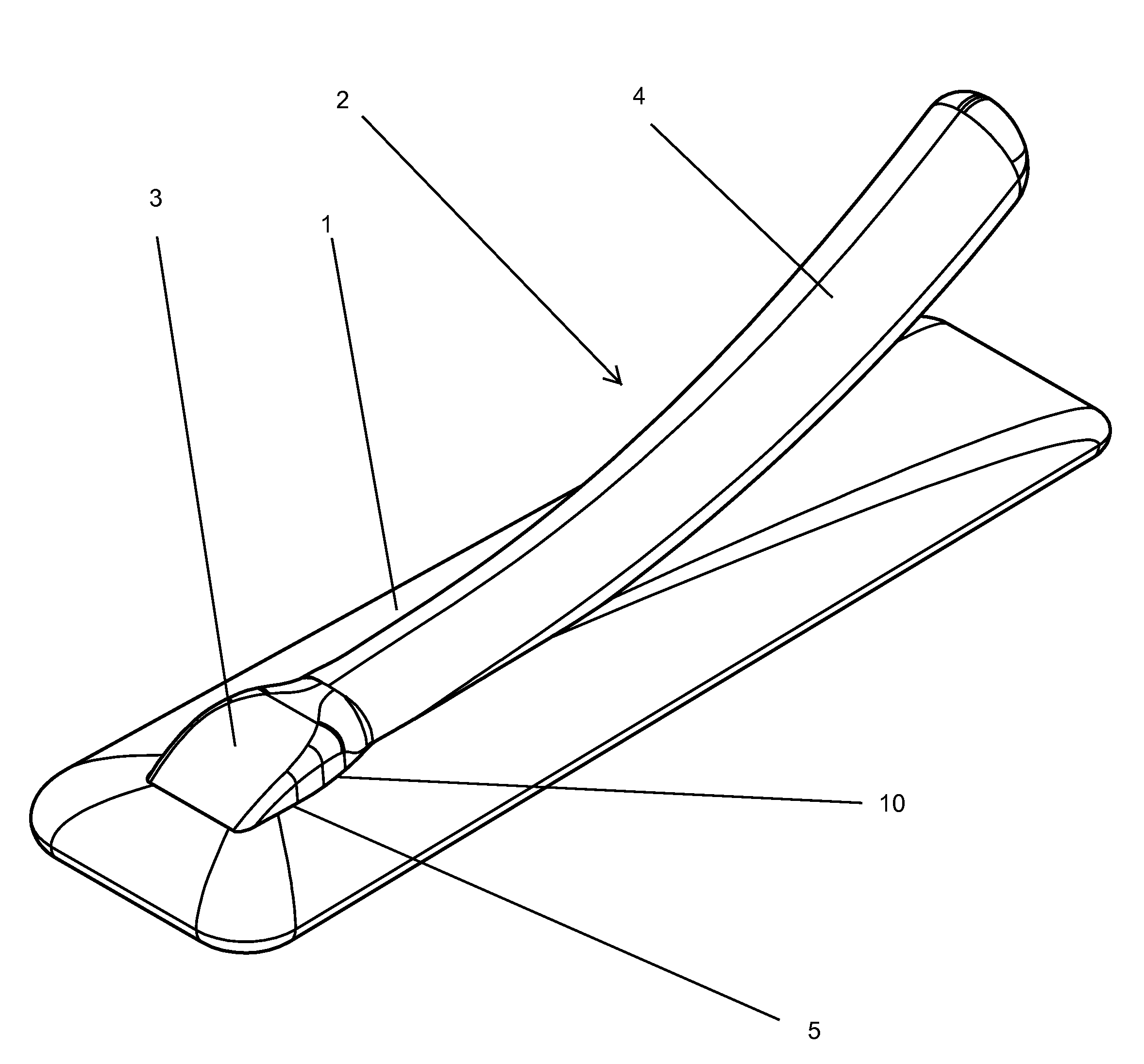
[0019]FIG. 1 shows an isometric view of the holding device according to the invention with a scanner 2. A base element 1 of the holding device accommodates the scanner 2 in the area of the scanner head 3 and partially in the area of the scanner grip 4 in a receiving area 5.

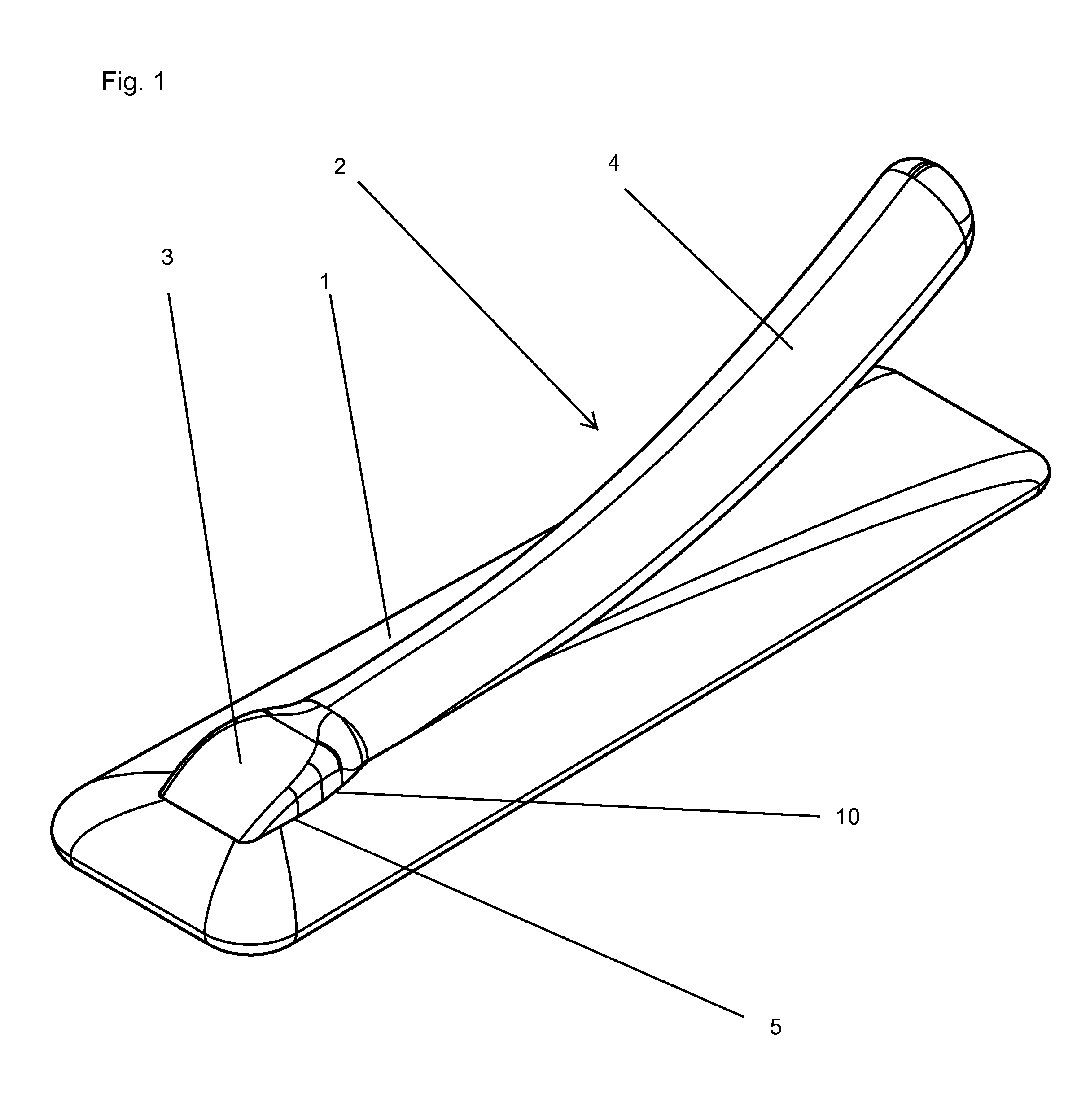
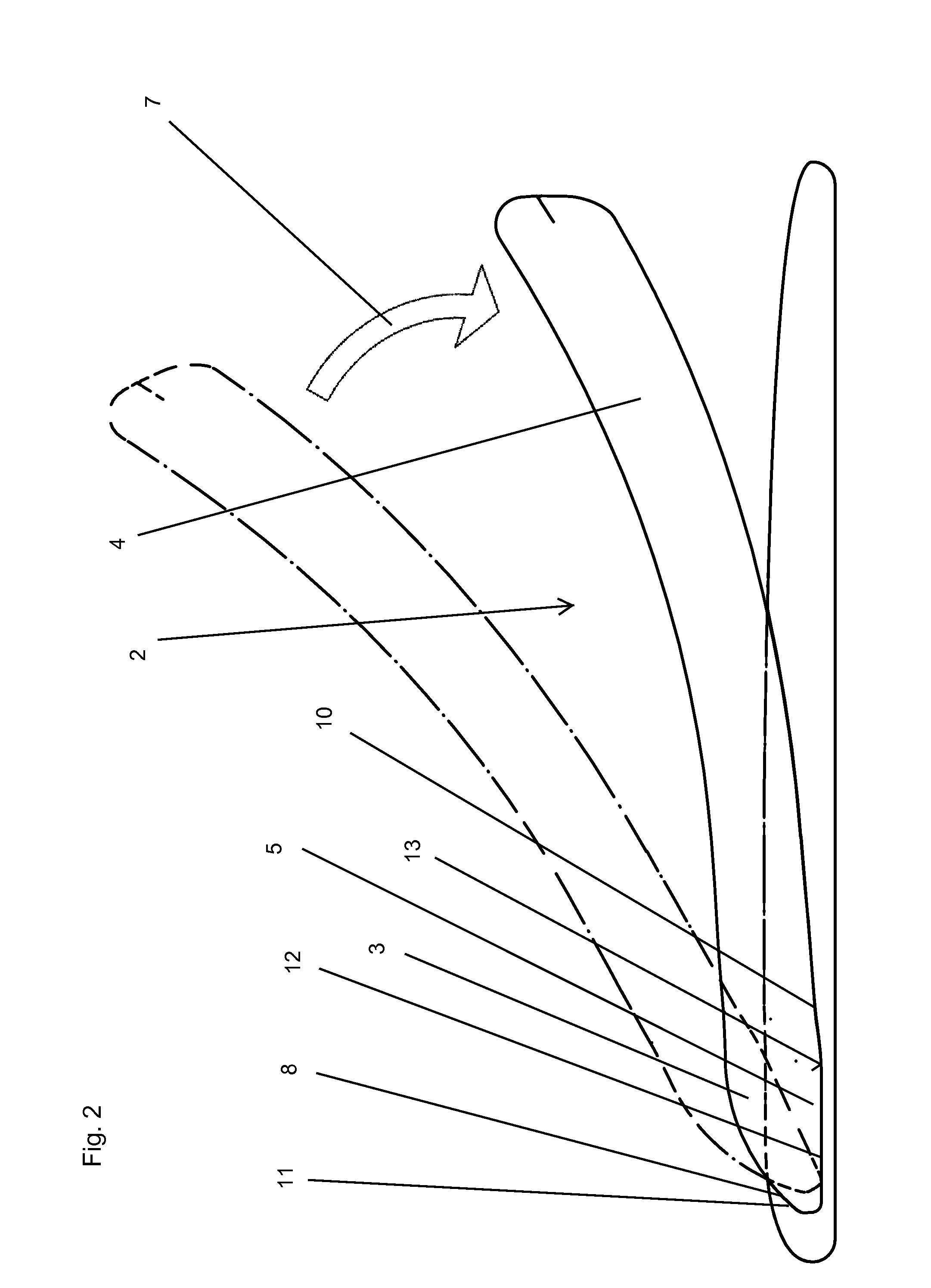
[0020]FIG. 2 shows a schematized longitudinal section, through the embodiment of FIG. 1. In this case, a scanner border 6 in dashed-dotted lines shows the beginning of a deposition movement being carried out in the direction of an arrow 7. This can be performed easily and intuitively. No complicated locking mechanisms, which would configure the handling less comfortably for the user, are necessary.

[0021]FIG. 2 further shows the contour of an interior 8 of the receiving area 5. The latter has two holding areas 10, 11 that are essentially opposite to one another. In this case, the rear holding area 10 receives the weight of the scanner 2 and stretches laterally upward, as FIG. 1 shows. In this case, the front holdin...

second embodiment

[0025]FIG. 5 shows a schematized view of FIGS. 3 and 4 with a scanner 2 from above. The calibrating element 19 with the calibrating pattern 21 is detected below the work area 12 of the scanner head 3. Embodiments in which the heating element and the calibrating element are designed in one piece, for example by a heating element that is printed with a calibrating pattern, are also conceivable. Footings 22 are discernible below the base element 1. The latter can serve as supports for the base element 1 or else can be connected by friction or can be integral, for example via suction cups or else adhesive compounds, with a base, for example the treatment chair or a table surface.

[0026]FIG. 6 shows a longitudinal section through FIG. 5. The positions of the calibrating element 19 and the heating element 14 in the base element 1 are detected. In this case, the work area 12 associated with the base area 13 lies above the calibrating element 19. To this end, in this embodiment, a gap betwee...

third embodiment

[0030]FIG. 9 shows an isometric view of the holding device. In the latter, the base element 1 is not, as described in the preceding embodiments of the invention, arranged on a surface, but rather recessed in a surface, for example of a table or a treatment chair, and it has a mounting plate 9. The receiving area 5 in this case is recessed in the surface.

[0031]FIG. 10 shows a view of the third embodiment from the top. Heating or calibrating elements that are not depicted in this embodiment can also be installed in the base area 13. An exchange could then be carried out from the top before the scanner 2 is put into position.

[0032]FIG. 11 shows a section along the line XI-XI in FIG. 10. It is seen how the holding area 11 opposite to the holding area 10 is arranged open to the base area 13 in essentially a V shape. The thus comprised part of the interior 8 occupies the front part of the scanner head 2. The especially long rear area 23 of the receiving area 5 in this embodiment can be us...


PUM


Abstract

A holding device with a base element for a handpiece of an intraoral scanner, which has a head area (3), has a receiving area (5) of the base element (1), in which the head area (3) can be snugly accommodated at least partially. The receiving area (5) has an interior (8) with at least two holding areas (10, 11), which are arranged essentially opposite to one another.

Description

FIELD OF THE INVENTION[0001]The invention relates to a holding device with a base element for a handpiece of an intraoral scanner, which has a head area.BACKGROUND OF THE INVENTION[0002]Intraoral scanners are increasingly used in dental medicine, since they have many advantages relative to the conventional assessment of the dental structure of patients. Impressions, which are unpleasant for the patients, are eliminated, and radiation-based imaging methods such as X-rays can sometimes be avoided. The space requirement that is frequently substantial is disadvantageous, however, since many systems are available as integral devices in which a computer, monitor, and handpiece form a unit. In these embodiments, the scanner is run on a rolling cart to the treatment chair. Other systems can be operated with conventional computers. In such cases, the visual output of the scan is done via the normal computer display. The handpiece that is necessary in any case can then be connected, for examp...

Claims


Application Information

Patent Timeline
Patent Type & Authority Applications(United States)
IPC IPC(8): A61C9/00
CPCA61C9/0093A61B50/20A61C9/004A61G15/16A61C9/0046A61B2560/0456
Inventor JESENKO, JURGENISOLA, FRANZKOINIG, HORST
Owner A TRON3D
Why Eureka
Try Eureka