
Interior Step Ladder Rack

Inactive Publication Date: 2005-09-08
STABS DANIEL FREDRICK
View PDF23 Cites 10 Cited by
  • Summary
  • Abstract
  • Description
  • Claims
  • Application Information

AI Technical Summary

Benefits of technology

[0013] It is an object of the present invention to provide a ladder rack apparatus which allows loading and unloading of a ladder from a vehicle to occur in a timely and cost effective manner.
[0014] It is another object of the present invention to provide a ladder rack apparatus which is simple and easy to use.
[0017] It is a further object of the present invention to provide a ladder rack apparatus which provides for quick and easy placement of a ladder on the ladder rack.
[0018] It is another object of the present invention to provide a ladder rack apparatus which is inexpensive compared to prior art.
[0019] It is yet a further object of the present invention to provide a ladder rack apparatus which allows for a heavy ladder to be slid up into storage position while the ladder rack carries the entire weight of the ladder.
[0021] Generally, a sled-like design wherein the front of the rack is hingedly attached to the interior roofline ribs with a latch provided at the rear for securing a step ladder in the overhead space. The ladder rack is accessed from the rear doors or liftgate of a vehicle. The rear latch is opened allowing the rear of the ladder rack to drop to a desired height. A step ladder is loaded onto or unloaded from the ladder rack. The rear of the ladder rack is raised back up to the interior roofline and latched in place. The interior step ladder rack is especially useful to service vehicle operators as an aid in freeing vehicle floor space without requiring the use of a roof top rack.

Problems solved by technology

Ladders in general, and step ladders in particular, are often bulky and awkward to store.
Even simple overhead hooks can be troublesome for storage of heavy stepladders, and their use still requires the floor space below them be kept clear for access to the ladder.
Such racks are relatively costly and inconvenient to use.
They are not easy to reach and often require lifting heavy wooden ladders to the top of vehicles, resulting in occasional back injury.
These racks are usually open and expose the ladder to adverse weather conditions such as sun, snow, or rain.
Ladder rack designs which mount on the side of a service vehicle tend to block access to side doors or storage compartments.
Ladder rack designs which lower the ladder to an accessible height and retract for storage are bulky and expensive.
None of the prior art provides an overhead storage rack for securing a ladder for transportation and storage within the vehicle interior.
None of the prior art uses an interior overhead storage rack which provides easy access from the rear doors or liftgate of a vehicle.
None of the prior art uses a design which allows for a heavy ladder to be slid up into storage position while the rack carries the entire weight of the ladder.
None of the prior art uses a design where a single simple latching device completely secures the ladder rack and any ladder stored thereon for transportion.
This ladder rack apparatus is heavy, expensive, requires powered hydraulics to operate, and is designed primarily for use on emergency vehicles, and is not designed to provide simple interior storage of a ladder in a vehicle.
This ladder rack apparatus provides for exterior storage of a ladder using complex moving parts, and is not designed to provide simple interior storage of a ladder in a vehicle.
These designs do not provide for safe, low height lifting or simple interior storage of a ladder in a vehicle.
This design does not provide for safe, low height lifting or simple interior storage of a ladder in a vehicle.
This design does not provide for overhead storage of a ladder within the vehicle interior and does not provide for visual inspection of the ladder without complete removal from the vehicle.
This storage apparatus does not provide for a design within which a step ladder may be secured from movement for transportation.
This storage apparatus does not provide for a design which allows quick and easy placement of a step ladder on the apparatus.
This storage apparatus does not provide for a design which allows for a heavy ladder to be slid up into storage position, while the apparatus carries the entire weight of the ladder.

Method used


Image

  • Interior Step Ladder Rack
  • Interior Step Ladder Rack
  • Interior Step Ladder Rack

Examples


Embodiment Construction

[0036] Reference is made herein to the attached drawings. Like reference numerals are used throughout the various drawings to depict like or similar elements of the claimed ladder rack apparatus. For the purpose of presenting a brief and clear discussion of the ladder rack apparatus, the preferred embodiment will be discussed in conjunction with use in a service vehicle. This is for representative purposes only and should not be construed as limiting in any manner.

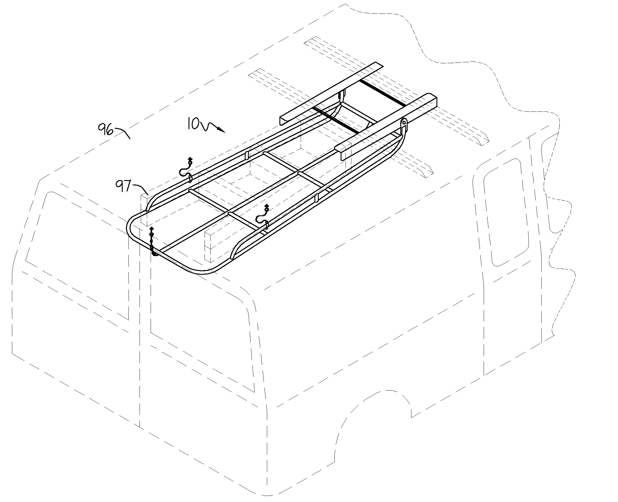
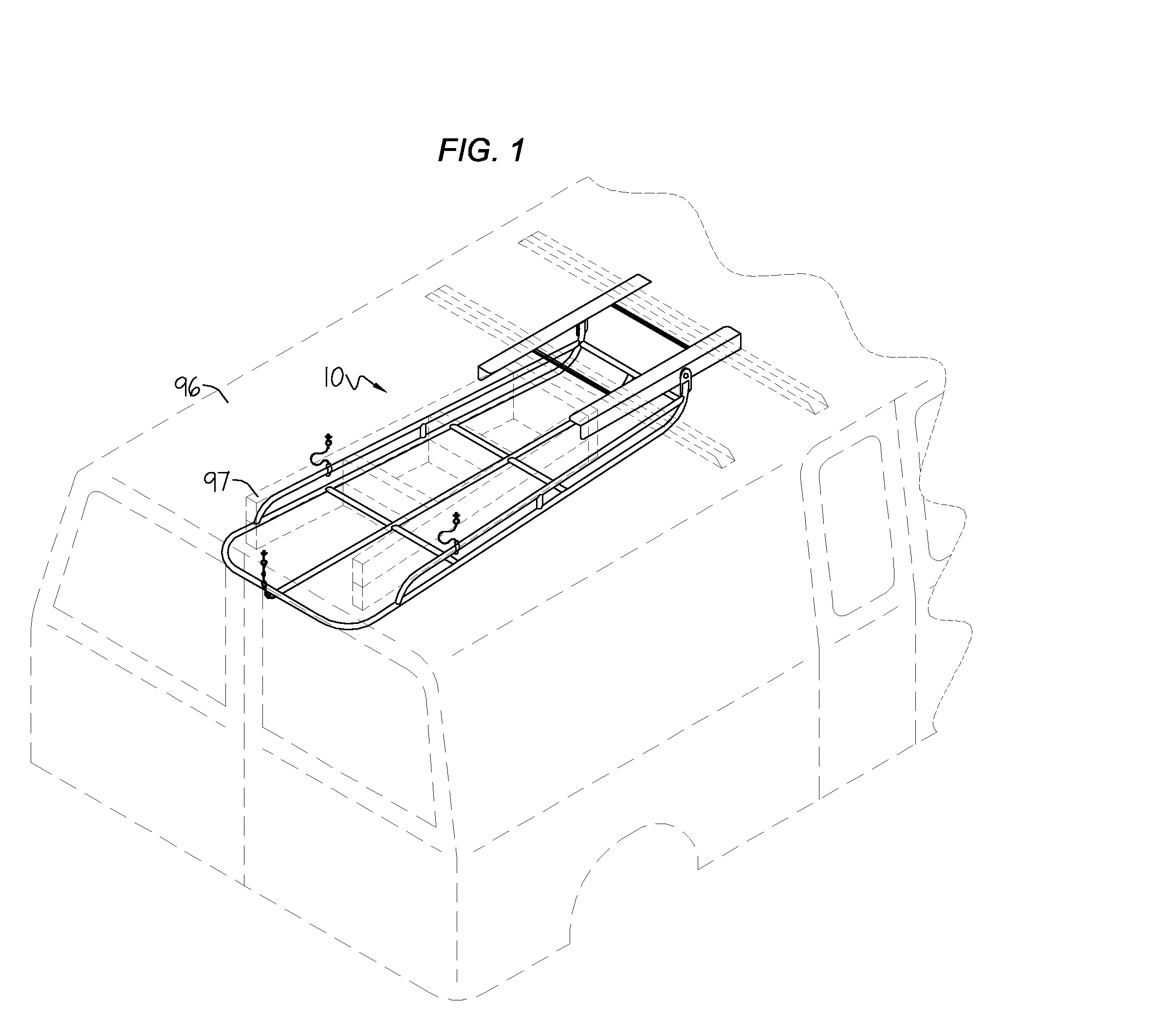
[0037] Referring now to FIG. 1, the preferred embodiment 10 of the ladder rack apparatus, is seen as positioned in the rear of a service van 96 with a ladder 97 in the closed or storage position.

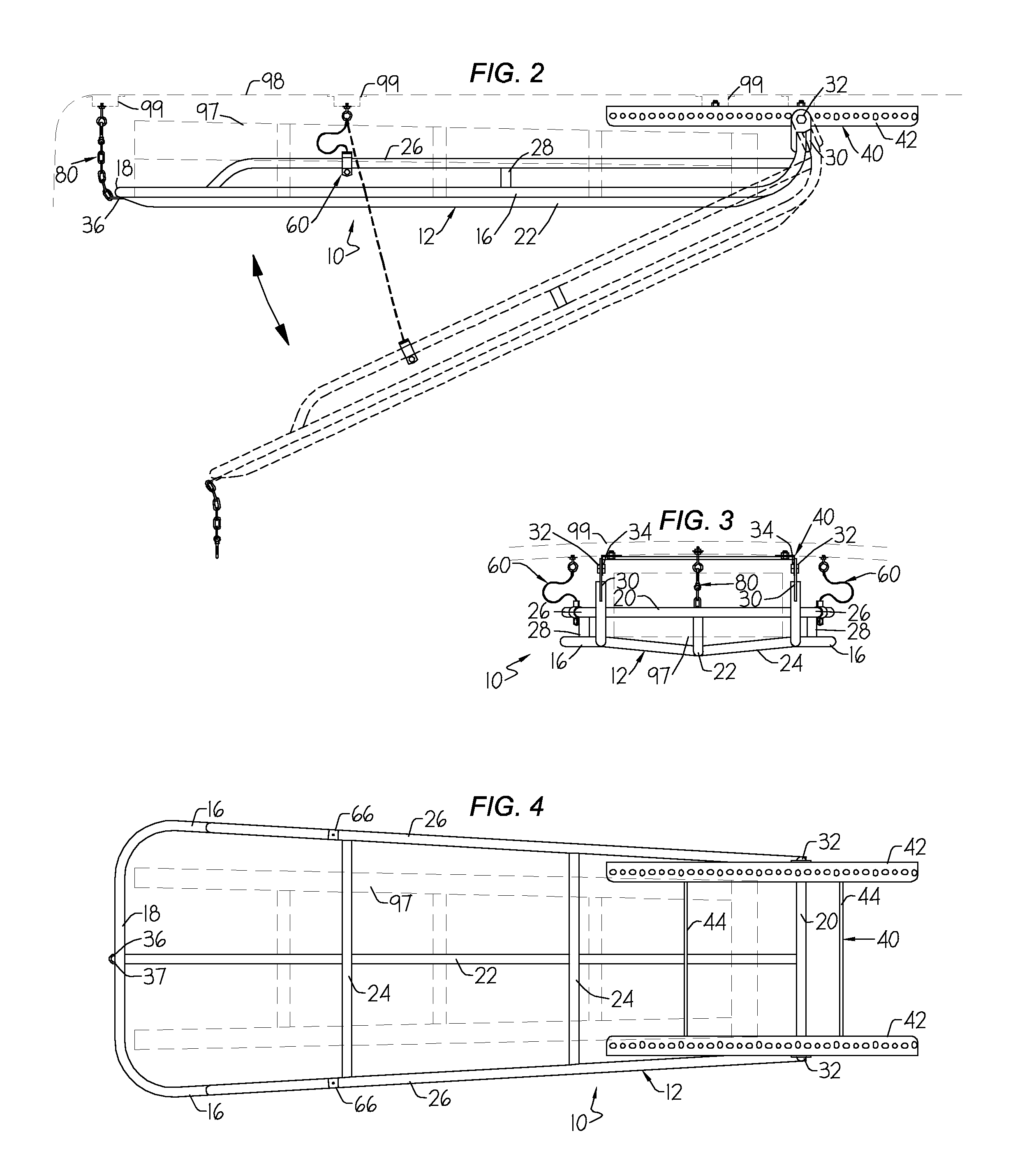
[0038]FIGS. 2, 3 and 4 provide greater detail of the ladder rack apparatus 10 with its primary assemblies: the ladder rack tube frame 12, which provides support for a ladder 97 which is stored on the ladder rack apparatus 10; the mounting assembly 40 which attaches to the service van's interior structural ribs 99, underneath the ...


PUM


Abstract

A ladder rack apparatus and method that allows a person to easily store a step ladder within the interior overhead space of a work vehicle. Generally, a sled-like design wherein the front of the rack is hingedly attached to the interior roofline with a latch provided at the rear for securing a step ladder in the overhead space. The ladder rack is accessed from the rear doors or liftgate of a vehicle. The rear latch is opened allowing the rear of the ladder rack to drop to a desired height. A step ladder is loaded onto or unloaded from the ladder rack. The rear of the ladder rack is raised back up to the interior roofline and latched in place. The interior step ladder rack is especially useful to service vehicle operators as an aid in freeing vehicle floor space without requiring the use of a roof top rack.

Description

BACKGROUND OF THE INVENTION [0001] The present invention relates in general to a ladder rack apparatus and method for overhead storage of a step ladder, and in particular to an interior step ladder rack apparatus for overhead storage of a step ladder within the interior space of a service vehicle. [0002] Ladders in general, and step ladders in particular, are often bulky and awkward to store. Usually ladders of any type are simply laid on the floor against a wall or suspended from the ceiling or wall on hooks. Even simple overhead hooks can be troublesome for storage of heavy stepladders, and their use still requires the floor space below them be kept clear for access to the ladder. For example, in order to lift a heavy step ladder onto overhead hooks, one must either stand and lift near the ladder's center or, with the help of an assistant, lift the ladder at opposite ends. In either case, it is necessary that the floor space below the hooks be clear or that the floor space at both...

Claims


Application Information

Patent Timeline
IPC IPC(8): B60P9/00
CPCB60R11/00B60R2011/0082B60R2011/0071B60R2011/0028
Inventor STABS, DANIEL FREDRICK
Owner STABS DANIEL FREDRICK
Learn More