
Linear motion system with automatic lubricator

Active Publication Date: 2014-09-18
HIWIN TECH
View PDF10 Cites 4 Cited by
  • Summary
  • Abstract
  • Description
  • Claims
  • Application Information

AI Technical Summary

Benefits of technology

The present invention is a linear motion system with an automatic lubricator. The system includes an elongated shaft, a movable member, rolling elements, a lubricator unit, and a sensor. The lubricator unit stores lubricating grease and discharges it onto the rolling elements and the shaft when the movable member moves. The sensor triggers the motor to start when the movable member moves, causing the lubricating grease to be applied automatically. The system aims to prevent unnecessary waste and save cost.

Problems solved by technology

In the case of the aforementioned patent, regardless of the linear transmission system is in operation, the motor F keeps rotating the helical blade 61 to continuously deliver the lubricating grease to the surface of the elongated shaft 1, causing unnecessary waste and increasing the cost.

Method used


Image

  • Linear motion system with automatic lubricator
  • Linear motion system with automatic lubricator
  • Linear motion system with automatic lubricator

Examples


first embodiment

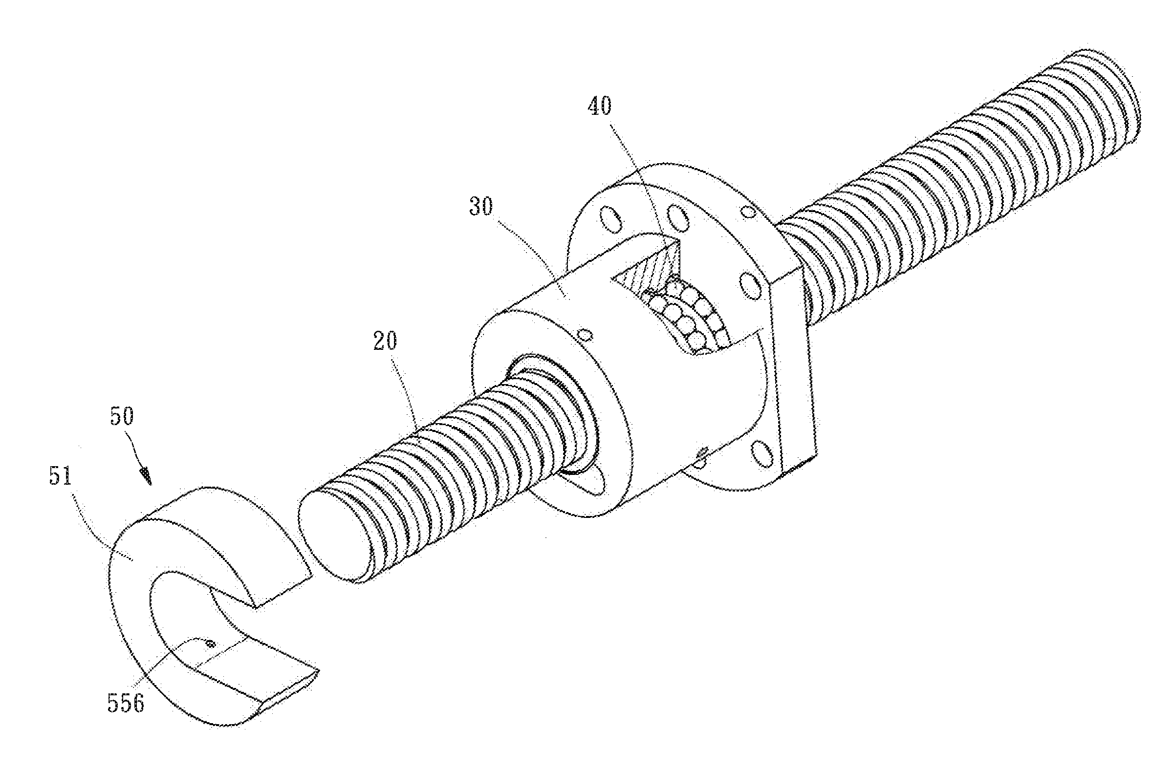
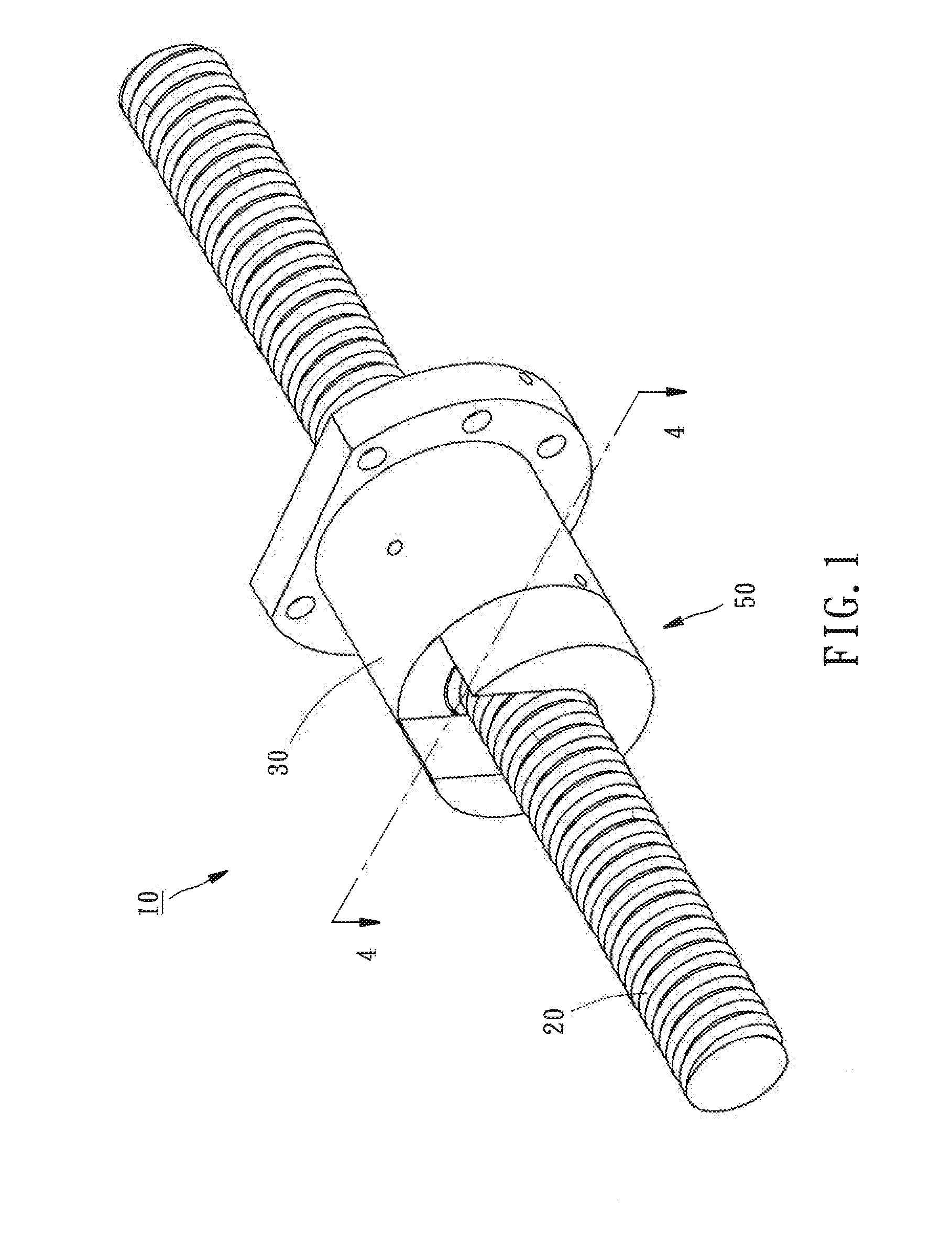
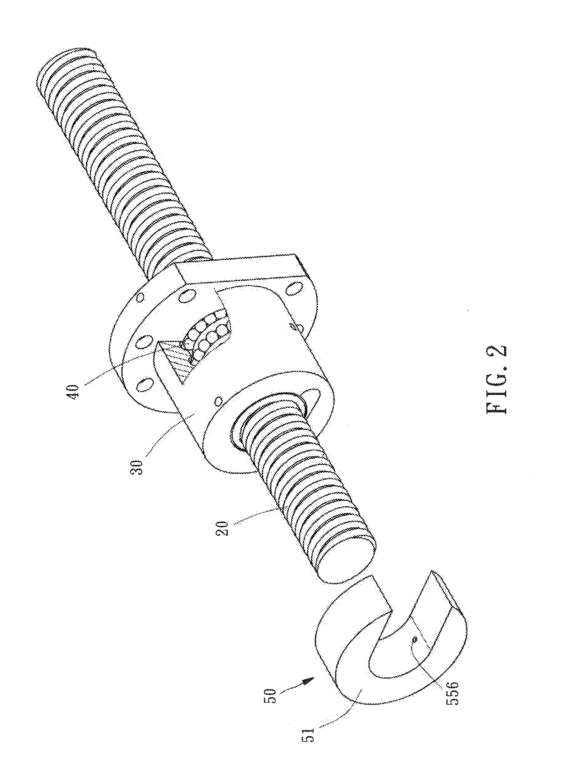
[0020]Referring to FIGS. 1, 2 and 4, a linear motion system 10 in accordance3 with the present invention is shown. As illustrated, the linear motion system 10 comprises an elongated shaft 20, a movable member 30, a plurality of rolling elements 40, a lubricator unit 50, and a sensor 60. According to this embodiment, linear motion system 10 is a ball screw, and therefore, the elongated shaft 20 is a screw rod, and the movable member 30 is a screw nut.

[0021]The movable member 30 is rotatably mounted on the elongated shaft 20 and movable back and forth in axial direction along the elongated shaft 20, defining with the elongated shaft 20 a circulation passage 42 (see FIG. 3).

[0022]The rolling elements 40 are mounted in the circulation passage 42 and movable along the circulation passage 42 during movement of the movable member 30 relative to the elongated shaft 20.

[0023]Referring to FIG. 4 again, the lubricator unit 50 comprises a grease storage container 51, a motor 52, a lubricating g...

fourth embodiment

[0030]In conclusion, subject to the intermittent actuation signal provided by the sensor 60, the linear motion system 10 enables the controller 54 to determine whether the movable member 30 is in movement, and the controller 54 can control the lubricator unit 50 to dispense the lubricating grease only when the movable member 30 is in movement. When compared to the prior art design, the invention accurately prevents unnecessary waste and effectively saves the cost. Further, the linear motion system 10 in accordance with the present invention is not limited to the aforesaid ball screw. In the present invention, as shown in FIG. 11, the linear motion system is a linear guideway. In this case, the elongated shaft 20 is a sliding rail, and the movable member 30 is a sliding block. This design of linear guideway can also match with the lubricator unit 50 and the sensor 60 to achieve a self-lubricating effect.


PUM


Abstract

A linear motion system includes an elongated shaft, a movable member mounted at the elongated shaft, a lubricator unit defining therein a grease storage container for storing a lubricating grease, a motor mounted in the grease storage container, a lubricating grease guide connected to the motor, a controller mounted in the grease storage container, and a sensor adapted to provide an actuation signal to the controller upon movement of the movable member, causing the controller to start the motor in moving the lubricating grease guide to expel the storage lubricating grease out of the grease storage container onto the surface of the elongated shaft so as to achieve a self-lubricating effect.

Description

BACKGROUND OF THE INVENTION[0001]1. Field of the Invention[0002]The present invention relates to linear motion technology and more particularly, to a linear motion system with automatic lubricator.[0003]2. Description of the Related Art[0004]U.S. Pat. No. 8,302,499 discloses a linear transmission system with a lubrication device (the reference signs of the following components are quoted from the specification of the cited patent), which discloses the use of a motor F to rotate a helical blade 61, making a lubricating grease overflow to the surface of an elongated shaft 1 to perform lubrication synchronously during rotation of the helical blade 61.[0005]In the case of the aforementioned patent, regardless of the linear transmission system is in operation, the motor F keeps rotating the helical blade 61 to continuously deliver the lubricating grease to the surface of the elongated shaft 1, causing unnecessary waste and increasing the cost.SUMMARY OF THE INVENTION[0006]The present inv...

Claims


Application Information

Patent Timeline
IPC IPC(8): F16H25/22
CPCF16H25/2214F16H25/2204F16H57/0464F16H57/0497Y10T74/18576
Inventor JIANG, ZONG-SIANCHANG, CHE-KANG
Owner HIWIN TECH
Learn More