Component Deployment System

Active Publication Date: 2014-09-18
THE BOEING CO
View PDF14 Cites 77 Cited by
  • Summary
  • Abstract
  • Description
  • Claims
  • Application Information

AI Technical Summary

Problems solved by technology

Both the decrease in size of the satellite, as well as the type of launch vehicle used, decreases the cost of launching the satellite into orbit.
With smaller satellites, the storage capacity of the satellite may not be as

Method used


Image

  • Component Deployment System
  • Component Deployment System
  • Component Deployment System

Examples


Embodiment Construction

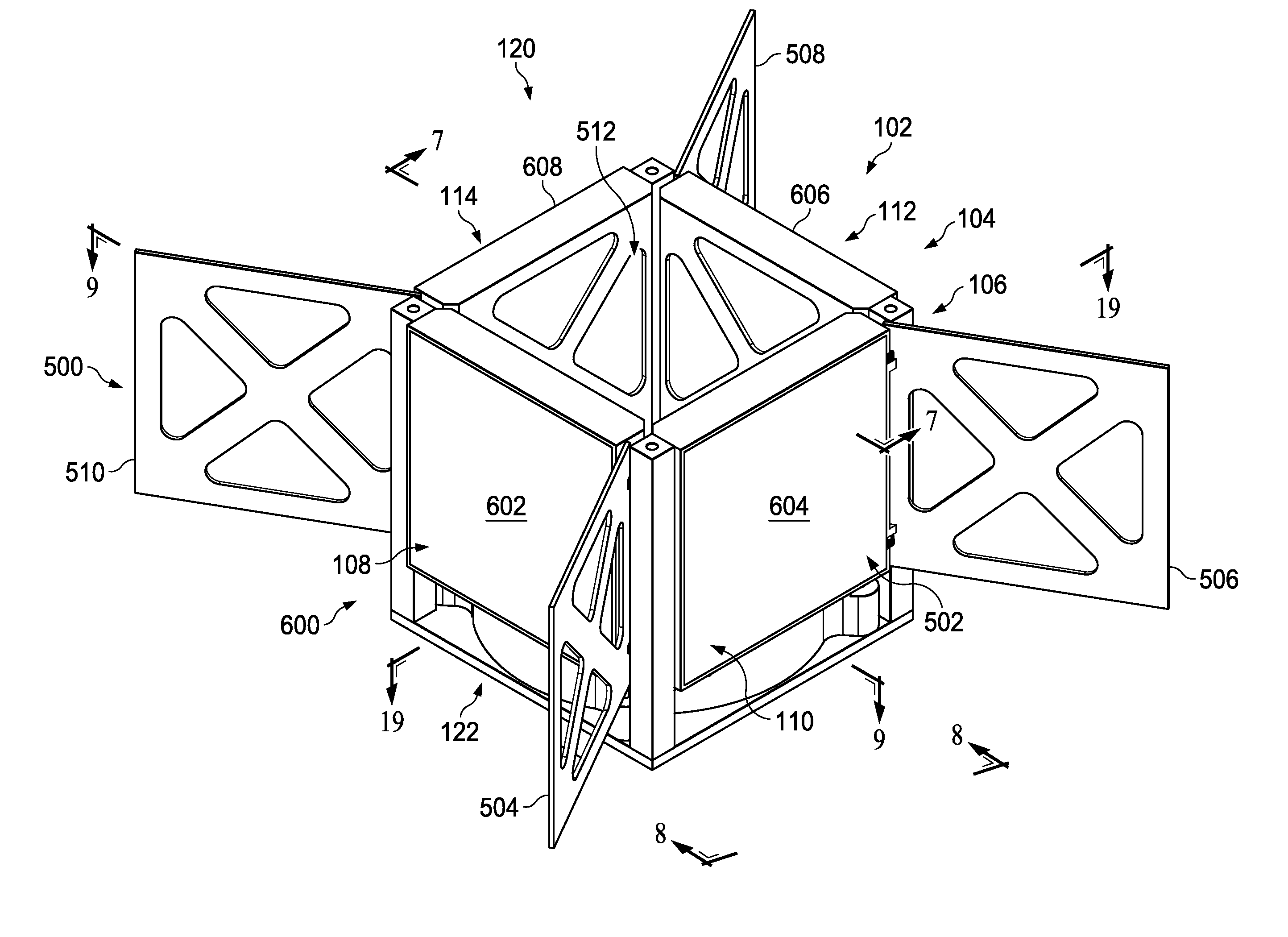
[0056]The illustrative embodiments recognize and take into account one or more different considerations. For example, the illustrative embodiments recognize and take into account that it may be desirable to increase the size of components that are deployed from a satellite. For example, the illustrative embodiments recognize and take into account that with larger solar panels deployed from the satellite, more power can be generated by the satellite. This increase in power may provide additional operating capabilities for the satellite, increase the functioning life of the satellite, or both. In a similar fashion, the illustrative embodiments recognize and take into account that increasing the size of an antenna deployed from a satellite increases the communication capabilities of that satellite.

[0057]The illustrative embodiments recognize and take into account, however, that some currently used deployment systems for deploying components from a satellite include structures that may ...


PUM


Abstract

A method and apparatus for deploying a group of panels. An apparatus comprises a group of panels in a folded configuration against a side of a spacecraft, a group of flexible members connected to the group of panels, and an interface system associated with the group of panels and the group of flexible members. The interface system is configured to move the group of panels from the folded configuration to a deployed configuration when the group of flexible members is extended from the spacecraft.

Description

RELATED PROVISIONAL APPLICATION[0001]This application claims the benefit of U.S. Patent Application Ser. No. 61 / 799,231, attorney docket no. 1406-003.001, entitled “Solar Arrays and Deployment Mechanisms for Solar Arrays,” filed Mar. 15, 2013, which is incorporated herein by reference in its entirety.BACKGROUND INFORMATION[0002]1. Field[0003]The present disclosure relates generally to deploying components and, in particular, to systems for deploying components. Still more particularly, the present disclosure relates to a method and apparatus for deploying components from a spacecraft.[0004]2. Background[0005]Spacecraft are used for various purposes while in space. A spacecraft, as used herein, is a vehicle, vessel, or machine configured to perform a number of operations in space. Spacecraft may be self-propelled space vehicles configured for short-term space missions, or space vehicles that are configured to remain in space for a longer period of time. In other cases, a spacecraft m...

Claims


Application Information

Patent Timeline
IPC IPC(8): B64G1/22H01L31/04H01Q1/28H01Q1/08B64G1/44B64G1/28
CPCB64G1/222B64G1/44H01L31/0413H01Q1/288H01Q1/08B64G1/28B64G1/10B64G1/62B64G1/66H01Q15/161H02S30/20Y02E10/50B64G1/22H02S20/30
Inventor COOK, JR., HUGH QUENTENSTREETT, ANDREW R.
Owner THE BOEING CO
Why Eureka
Try Eureka