Intelligent Door Lock System

a door lock and intelligent technology, applied in the field of intelligent door lock devices, can solve the problems of theft, unauthorized entry, easy to improperly depress the release of the lock by itself,

Active Publication Date: 2014-09-18
AUGUST HOME
View PDF3 Cites 405 Cited by
  • Summary
  • Abstract
  • Description
  • Claims
  • Application Information

AI Technical Summary

Benefits of technology

The present invention is an intelligent door lock system that uses a position sensing device to determine if someone has used a key or a lock pick. The system includes a drive shaft and a device that converts energy into mechanical energy. The position sensing device is coupled to the drive shaft and the energy source provides energy to the device. The device that converts energy is coupled to the energy source to receive energy from the energy source. The technical effect of this invention is to provide an efficient and effective door lock system that can detect and prevent unauthorized access.

Problems solved by technology

The technical problem addressed in this patent text is the need for a door lock system that can be retrofitted to an existing door, and can be locked and unlocked electronically, automatically, and remotely. There is also a need for an intelligent door lock system that can detect the position of the dead bolt and the depth of its travel, and can be repositioned in an absolute state.

Method used


Image

  • Intelligent Door Lock System
  • Intelligent Door Lock System
  • Intelligent Door Lock System

Examples


Embodiment Construction

[0056]As used herein, the term engine refers to software, firmware, hardware, or other component that can be used to effectuate a purpose. The engine will typically include software instructions that are stored in non-volatile memory (also referred to as secondary memory). When the software instructions are executed, at least a subset of the software instructions can be loaded into memory (also referred to as primary memory) by a processor. The processor then executes the software instructions in memory. The processor may be a shared processor, a dedicated processor, or a combination of shared or dedicated processors. A typical program will include calls to hardware components (such as I / O devices), which typically requires the execution of drivers. The drivers may or may not be considered part of the engine, but the distinction is not critical.

[0057]As used herein, the term database is used broadly to include any known or convenient means for storing data, whether centralized or di...


PUM


Abstract

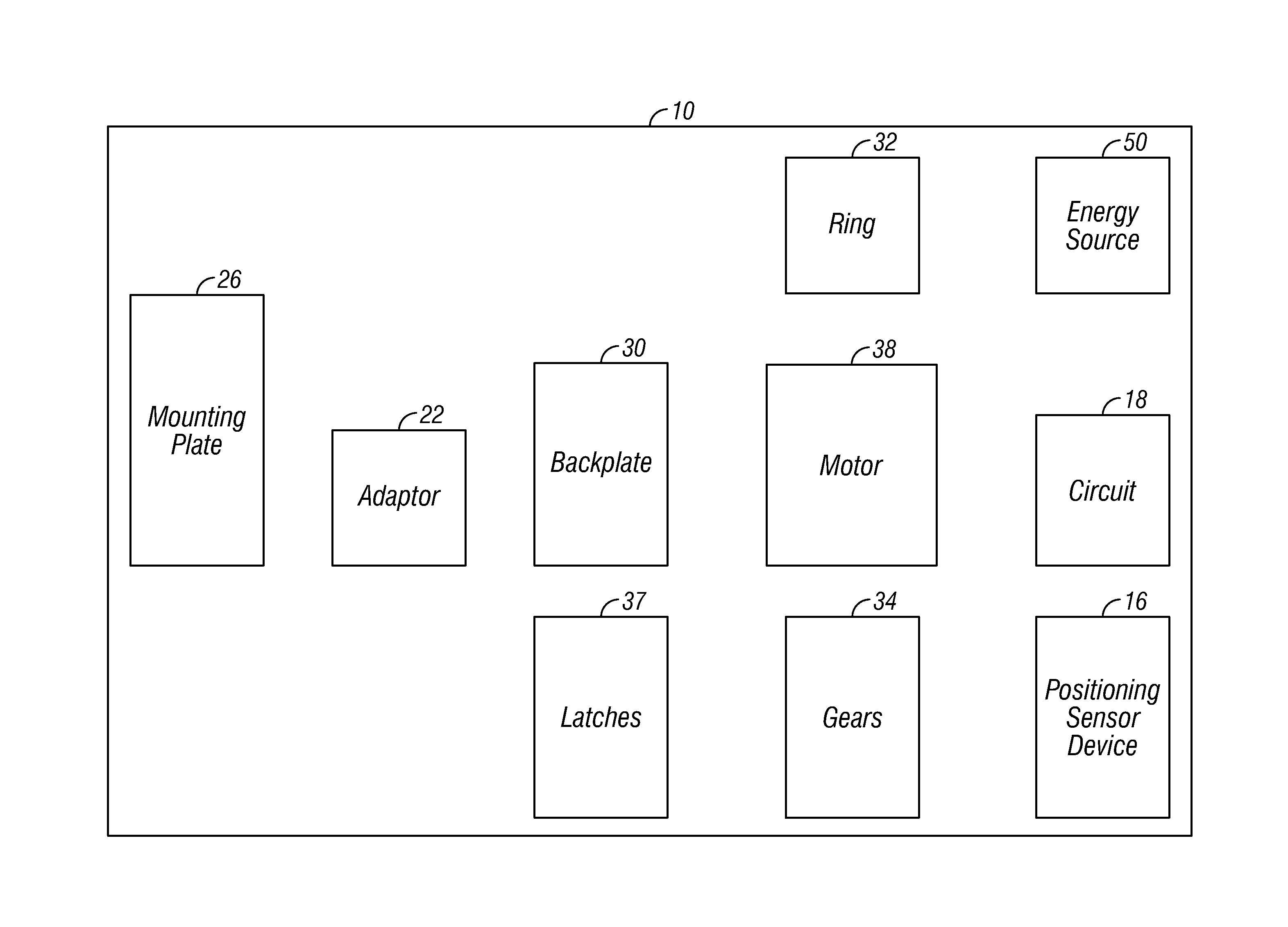
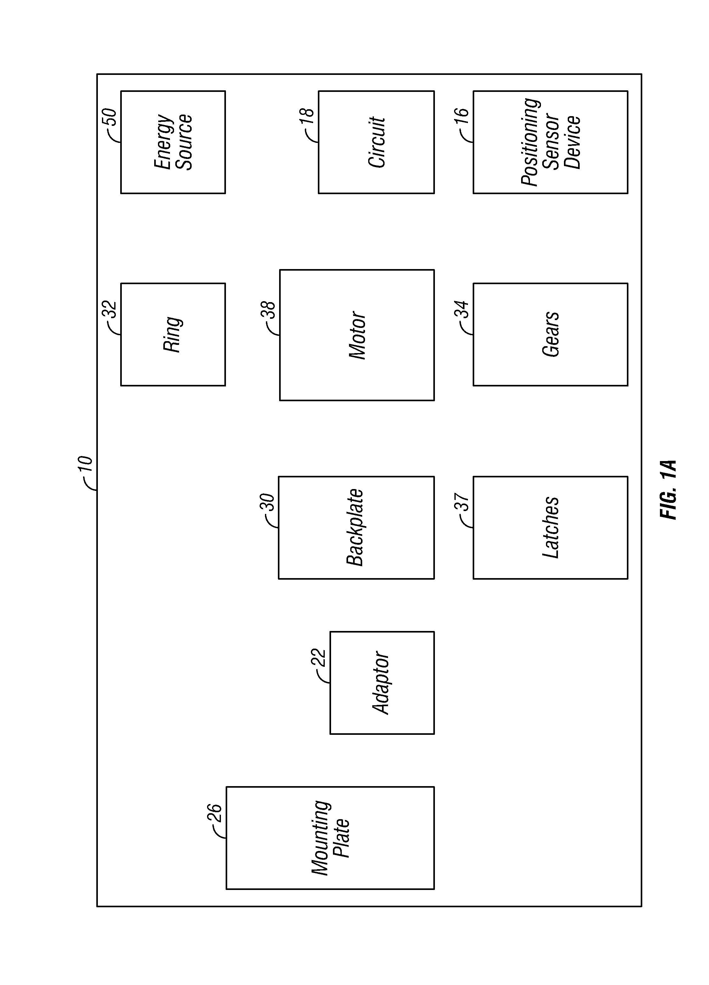
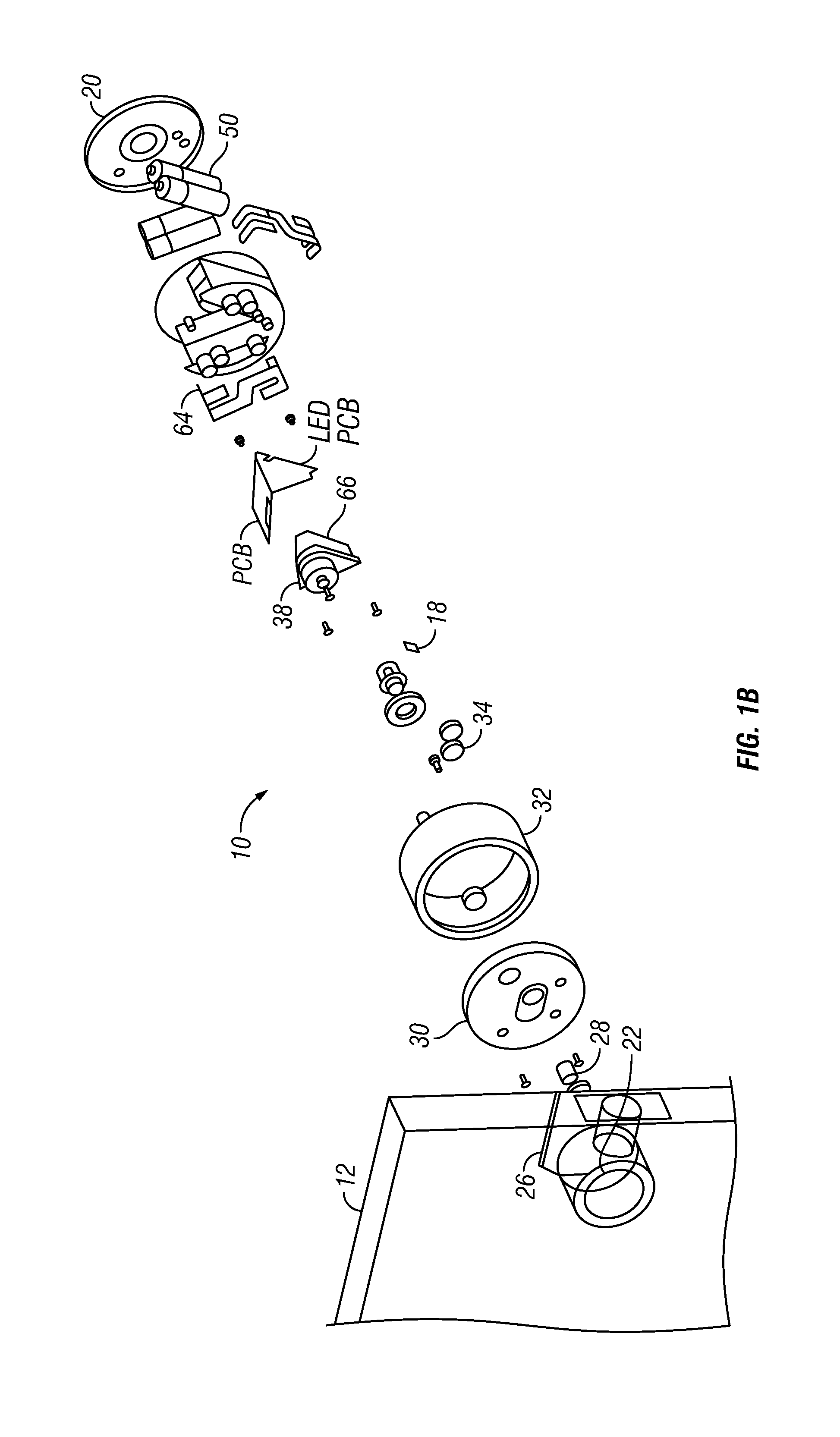
An intelligent door lock system is provided with a position sensing device configured to be coupled to a drive shaft of a lock device. The position sensing device senses position of the drive shaft and assists in locking and unlocking a lock of a lock device. An engine is provided with a memory coupled to the positioning sensing device. A circuit is coupled to the engine and an energy source is coupled to the circuit. A device converts energy into mechanical energy and is coupled to the circuit, positioning sensing device and the drive shaft. The device that converts energy is coupled to the energy source to receive energy from the energy source.

Description


Claims


Application Information

Patent Timeline
Owner AUGUST HOME
Why Eureka
Try Eureka