Apparatus and methods for two-dimensional and three-dimensional inspection of a workpiece

a technology of two-dimensional and three-dimensional inspection and workpiece, applied in the field of workpiece inspection, can solve the problems of unreliable, inefficient, subject to operator error, limited capacity to meet these requirements, and assumption proved unworkable in the real world,

Active Publication Date: 2008-03-06
THE BOEING CO
View PDF11 Cites 108 Cited by
  • Summary
  • Abstract
  • Description
  • Claims
  • Application Information

AI Technical Summary

Benefits of technology

[0009]Embodiments of the invention may address at least some of the above needs and achieve other advantages by providing apparatus and methods for inspecting a workpiece. Generally, embodiments of the present invention include apparatus and methods for interpreting images of a workpiece in order to characterize a feature identified on the workpiece. In particular, embodiments provide apparatus and methods for generating information indicative of the workpiece based on one or more images captured by a camera, wherein the images are generated in response to the illumination of the workpiece with one or more illumination sources. For instance, apparatus and methods of the present invention could be used to provide both two-dimensional and three-dimensional information indicative of the workpiece, analyze the illuminated portion of the workpiece despite the presence of noise, and locate and classify various features associated with the workpiece.

Problems solved by technology

Prior and emerging art, using various machine vision technologies, have provided limited capabilities to meet these requirements.
As such, manual visual inspection of composite plies is frequently employed, which may be unreliable, inefficient, and subject to operator error.
The original presumption was that the expected laser line signatures seen during normal manufacturing would be well-known, and any variance from a “perfect” signature constituted a detected defect.
This assumption proved unworkable in the real world once prototype systems were built and tested on an actual composite tape lay-up machine.
For instance, the optical appearance of the composite materials is not as consistent as obtained from coupons that have been examined earlier in the laboratory and vary greatly in reflectivity degree and sensitivity to fiber orientation.
In addition, the working distance from the camera to the workpiece varies significantly, which causes the laser signature to move completely through the vertical extent of the camera frame, rather than remaining near the centerline of the image height.
While the camera's depth of field is easily controlled by modifying the lens, the depth of field of the laser generator cannot be changed such that the imaged laser signature is often out of focus.
Moreover, the actual working depth of field is at times transited at very high velocity (i.e., there are sharp “bumps” in the surface of the workpiece in addition to slowly-changed “swells”), which produces significant motion blur in the vertical image direction as the laser signature sweeps through the field.
The surface of the workpiece is not always flat, resulting in laser signatures that are rarely straight lines.
Furthermore, methods of FOD detection and classification that depend upon two-dimensional machine vision algorithms are defeated by the presence of a strong laser line signature.

Method used


Image

  • Apparatus and methods for two-dimensional and three-dimensional inspection of a workpiece
  • Apparatus and methods for two-dimensional and three-dimensional inspection of a workpiece
  • Apparatus and methods for two-dimensional and three-dimensional inspection of a workpiece

Examples


Embodiment Construction

[0029]The present invention now will be described more fully hereinafter with reference to the accompanying drawings, in which some, but not all embodiments of the invention are shown. Indeed, the invention may be embodied in many different forms and should not be construed as limited to the embodiments set forth herein; rather, these embodiments are provided so that this disclosure will satisfy applicable legal requirements. Like numbers refer to like elements throughout.

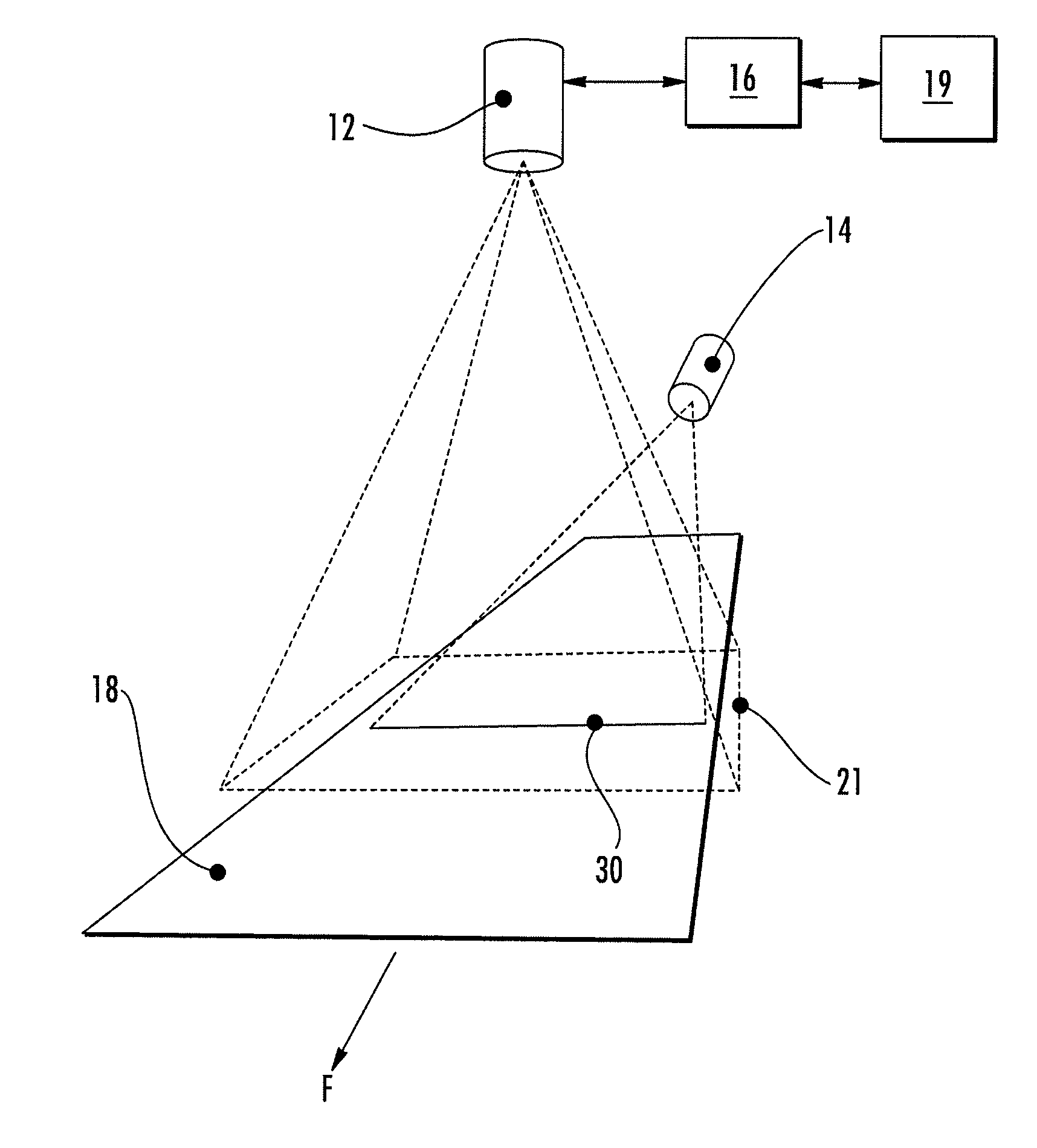
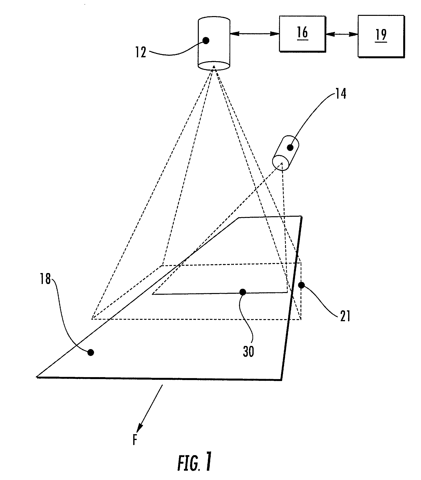
[0030]Referring now to the drawings and, in particular to FIG. 1, there is shown an inspection system 10 for identifying and locating features in a workpiece. The system 10 includes a camera 12 and at least one illumination source 14, in some combination determined by the type of workpiece to be inspected, that acquire data indicative of the workpiece 18. The camera 12 and illumination source 14 are in communication with a data system 16 such that the data system may provide and / or process data captured by the came...


PUM

PropertyMeasurementUnit
incidence angleaaaaaaaaaa
incidence anglesaaaaaaaaaa
thicknessaaaaaaaaaa

Abstract

Apparatus and methods for inspecting a workpiece are provided. According to one embodiment, a method for inspecting a workpiece comprises illuminating at least a portion of the workpiece with at least one illumination beam and capturing at least one image including at least on line signature formed by illuminating the workpiece with the illumination beam. The method further includes performing two-dimensional and three-dimensional processes on the captured image and classifying at least one feature associated with the workpiece based at least in part on data generated by the two-dimensional and three-dimensional processes.

Description

BACKGROUND OF THE INVENTION[0001]1) Field of the Invention[0002]Embodiments of the present invention relate to the inspection of a workpiece and, more particularly, to apparatus and methods for providing two-dimensional and three-dimensional information indicative of a workpiece.[0003]2) Description of Related Art[0004]Composite structures are commonly manufactured by progressively building up the structure with a plurality of layers of thin composite tape (or tow) laid one layer upon another. Typically, the operation begins by laying one or more tapes onto a starting template or tool that has a configuration generally corresponding to the desired shape of the article to be produced. A tape placement head of a manufacturing system moves over the surface of the template, guiding the one or more tapes of composite material onto the template. The head usually makes repeated passes over the template in a defined pattern until the composite material is entirely collated, building up succ...

Claims


Application Information

Patent Timeline
Patent Type & Authority Applications(United States)
IPC IPC(8): G01N21/00
CPCB29C70/386G01N2021/8472G01N21/8901
Inventor WALTON, STEVEN R.
Owner THE BOEING CO
Why Eureka
Try Eureka