System for determining alignment of a user-marked document and method thereof

a document alignment and document technology, applied in the field of method of determining the alignment of a document, can solve the problems of low resolution, limited method, and current omr technology being limited to being able to read only pre-defined (i.e., fixed, parallel) positions

Active Publication Date: 2014-09-18
MEGAPIXEL SOFTWARE INC
View PDF4 Cites 8 Cited by
  • Summary
  • Abstract
  • Description
  • Claims
  • Application Information

AI Technical Summary

Benefits of technology

[0017]The converting of the identified spatial location coordinates

Problems solved by technology

However, there exists a problem in accurately identifying marked areas on scanned forms or other documents when using a non-fixed image capture device, having a relatively low resolution.
That is, current OMR technology is limited to being only able to read pre-defined (i.e., fixed, parallel) positions relative to the scanned form, generally using a border or “broken ladder” marks around the form for alignment.
However, this method only works well when the position of the camera and the page are both on the same plane, such as in the case of a desktop scanner or when using a fixed-position document

Method used


Image

  • System for determining alignment of a user-marked document and method thereof
  • System for determining alignment of a user-marked document and method thereof
  • System for determining alignment of a user-marked document and method thereof

Examples


Embodiment Construction

[0047]Reference will now be made in detail to the exemplary embodiments of the present general inventive concept, examples of which are illustrated in the accompanying drawings, wherein like reference numerals refer to the like elements throughout. The exemplary embodiments are described below in order to explain the present general inventive concept by referring to the figures.

[0048]The present general inventive concept relates to a method of aligning a user-marked document for optical mark recognition (“OMR”), and more particularly to a method of aligning, reading, and analyzing a user-marked document for OMR using a fixed or non-fixed image capturing device.

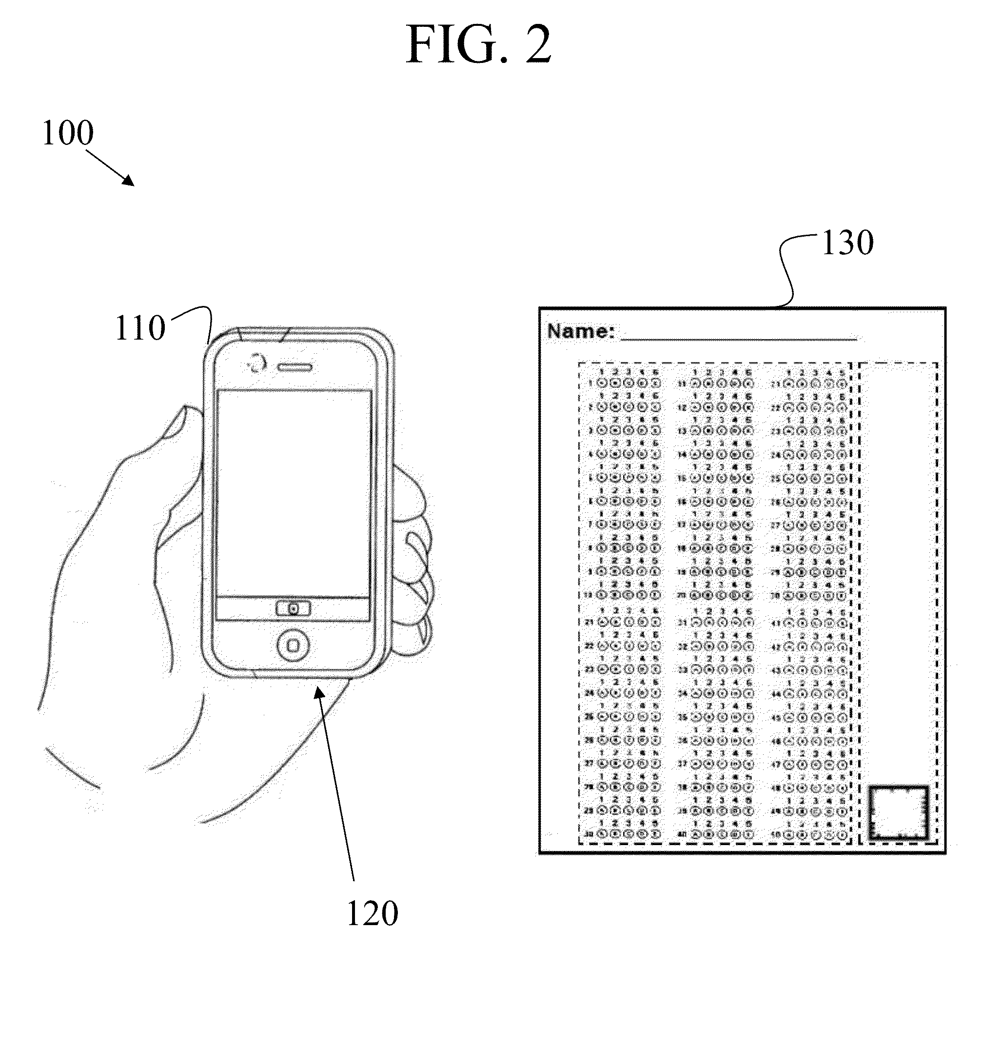
[0049]FIG. 2 illustrates a front perspective view of a non-fixed optical mark recognition system 100 according to an exemplary embodiment of the present general inventive concept. FIG. 3 illustrates a top plan view of a user-marked response sheet 130 according to an exemplary embodiment of the present general inventive concept...


PUM


Abstract

A system for evaluating a user-marked document including a user-marked response sheet having a response area and at least one image marker, a means for obtaining a digital image of the user-marked response sheet, a computer having programming to perform steps which include identifying three-dimensional position information of the at least one image marker in an obtained digital image, calculating position information of the response area in an obtained digital image using the three-dimensional position information of the at least one image marker, identifying position information of a user created mark within the response area using the calculated position information of the response area, and evaluating whether the position information of the user created mark corresponds with position information of a first predefined mark or a second predefined mark.

Description

CROSS-REFERENCE TO RELATED APPLICATIONS[0001]This application claims the benefit of U.S. Provisional Patent Application No. 61 / 618,262, filed on Mar. 30, 2012, the disclosure of which is incorporated herein in its entirety by reference.BACKGROUND OF THE INVENTION[0002]1. Field of the Invention[0003]The present general inventive concept relates to a method of determining alignment of a document for optical mark recognition (“OMR”), and more particularly to a method of determining alignment of a user-marked document for OMR using a non-fixed image capturing device. The present general inventive concept also relates a method of aligning a user-marked document for OMR using a non-fixed image capturing device, without requiring a de-skewing process.[0004]2. Description of Related Art[0005]Optical Mark Recognition (OMR) technology has been in use for decades. OMR is used to extract intended data from marked fields, such as check boxes and fill-in fields, on scanned forms or other document...

Claims


Application Information

Patent Timeline
IPC IPC(8): G06K9/18G06V30/224
CPCG06K9/18G06K5/04G06V10/245H04N23/63G06V30/224G06V30/412H04N23/00G06T7/90G06T5/003G06T19/006
Inventor KLEINMAN, DANIEL
Owner MEGAPIXEL SOFTWARE INC
Why Eureka
Try Eureka