

High-throughput routing in an optical network having a mesh topology
a technology of optical network and topology, applied in the field of optical communication equipment, can solve the problem of relatively difficult realization of scheduling types, and achieve the effect of straightforward optimization of optical routing layou
- Summary
- Abstract
- Description
- Claims
- Application Information
AI Technical Summary
Benefits of technology
Problems solved by technology
Method used
Image

Examples
Embodiment Construction
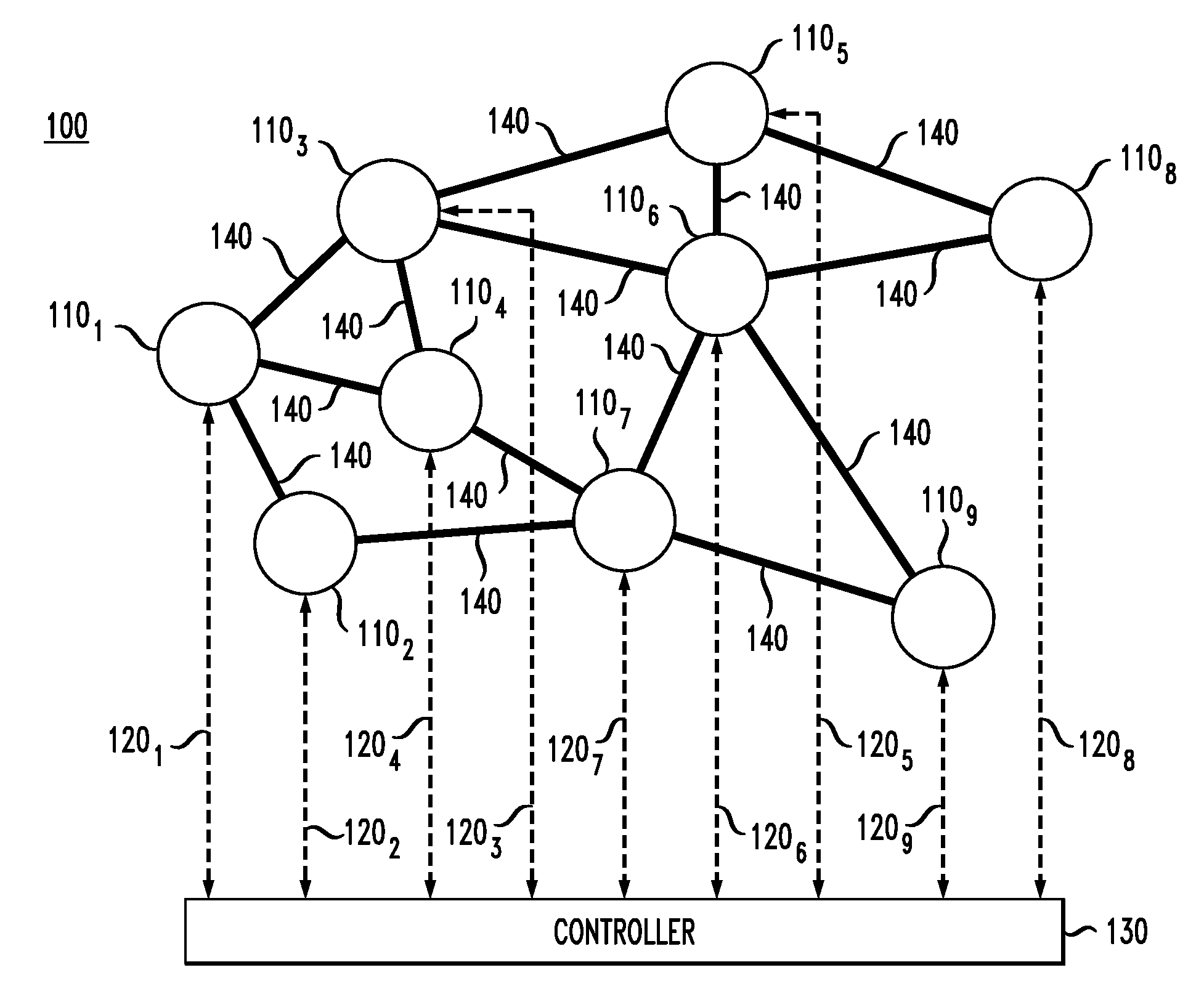
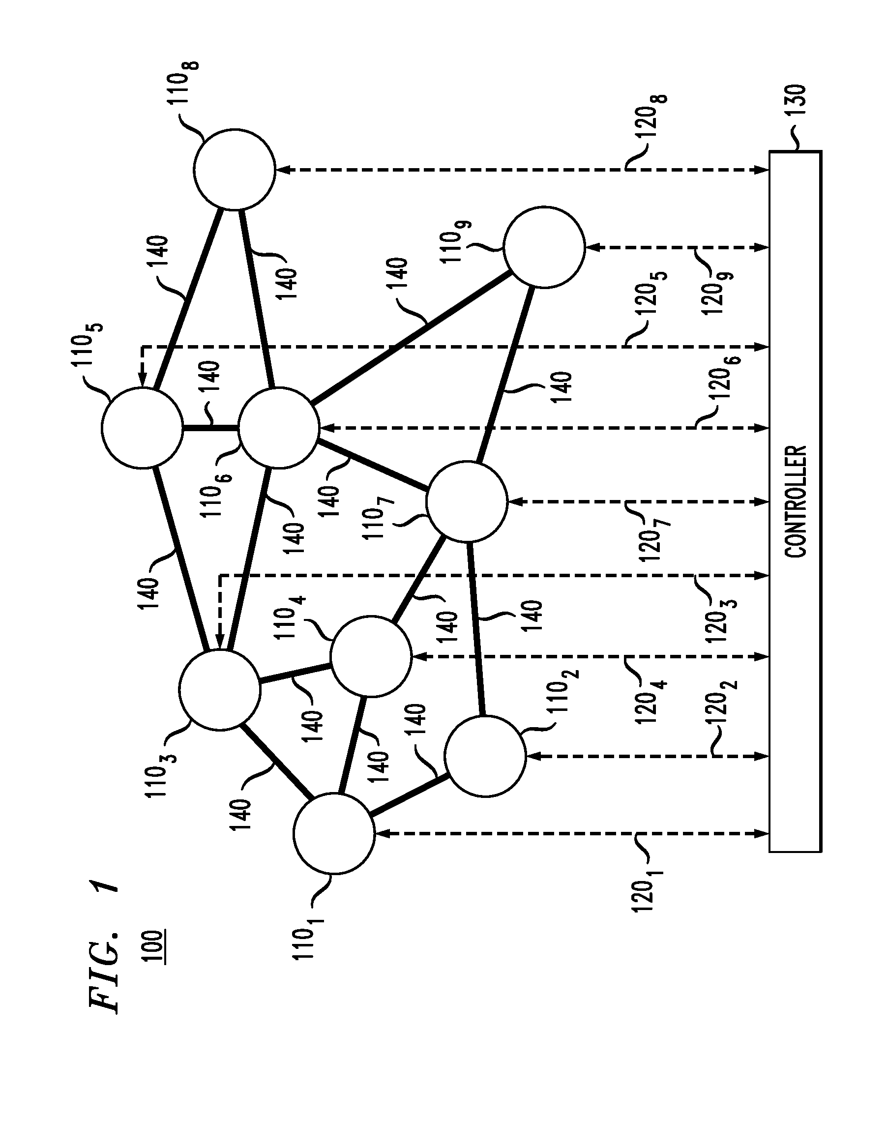
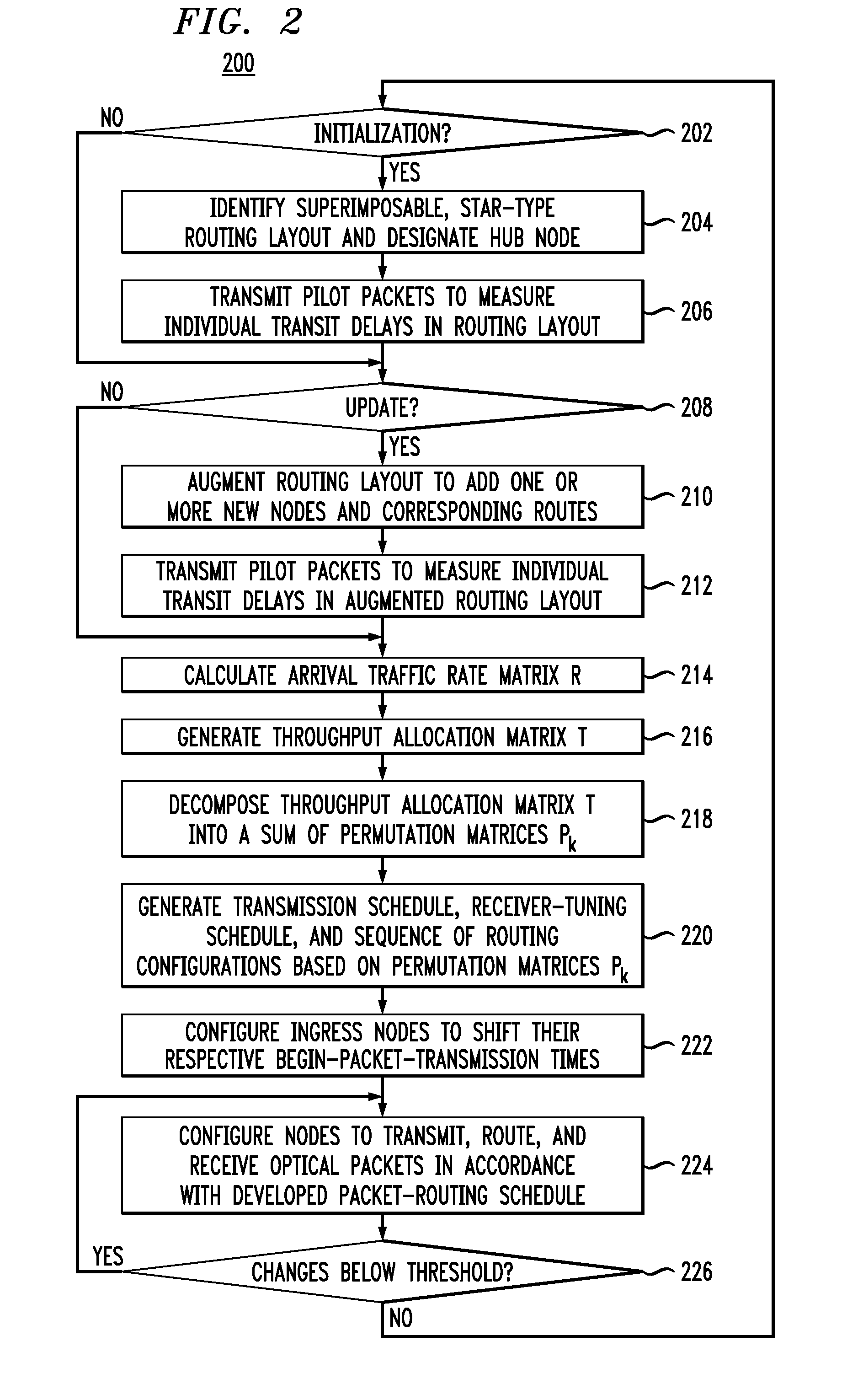
[0006]At least some of the above-indicated problems are addressed by an optical routing scheme in which an optical network having a mesh topology is configured to route optical packets through an optical routing layout superimposable with the mesh topology but having a star-like topology instead of the mesh topology. Using this optical routing layout, the optical network can be configured to transport optical packets from respective ingress nodes, through the hub node located at the star center, to respective egress nodes in a manner that enables a realizable data throughput that can closely approach the maximum theoretical capacity. Advantageously, no special hardware in addition to a wavelength-tunable transmitter, a wavelength-tunable receiver, and a wavelength-selective switch is required for the node to be amenable to the hub functionality, and any node of the optical network can in principle be configured to serve as the hub node. The latter feature enables relatively straight...
PUM
 Abstract
Description
Claims
Application Information