Fluid pump

a technology of fluid pump and upper bushing, which is applied in the direction of piston pump, positive displacement liquid engine, magnetic circuit shape/form/construction, etc., can solve the problem of difficulty in maintaining a sufficient coaxial relationship between the upper bushing and the lower bushing

Inactive Publication Date: 2014-10-23
DELPHI TECH IP LTD
View PDF6 Cites 29 Cited by
  • Summary
  • Abstract
  • Description
  • Claims
  • Application Information

AI Technical Summary

Problems solved by technology

Since separate tooling is used to manufacture the housing, the base of the motor and the outlet plate, it ma

Method used


Image

  • Fluid pump
  • Fluid pump
  • Fluid pump

Examples


Embodiment Construction

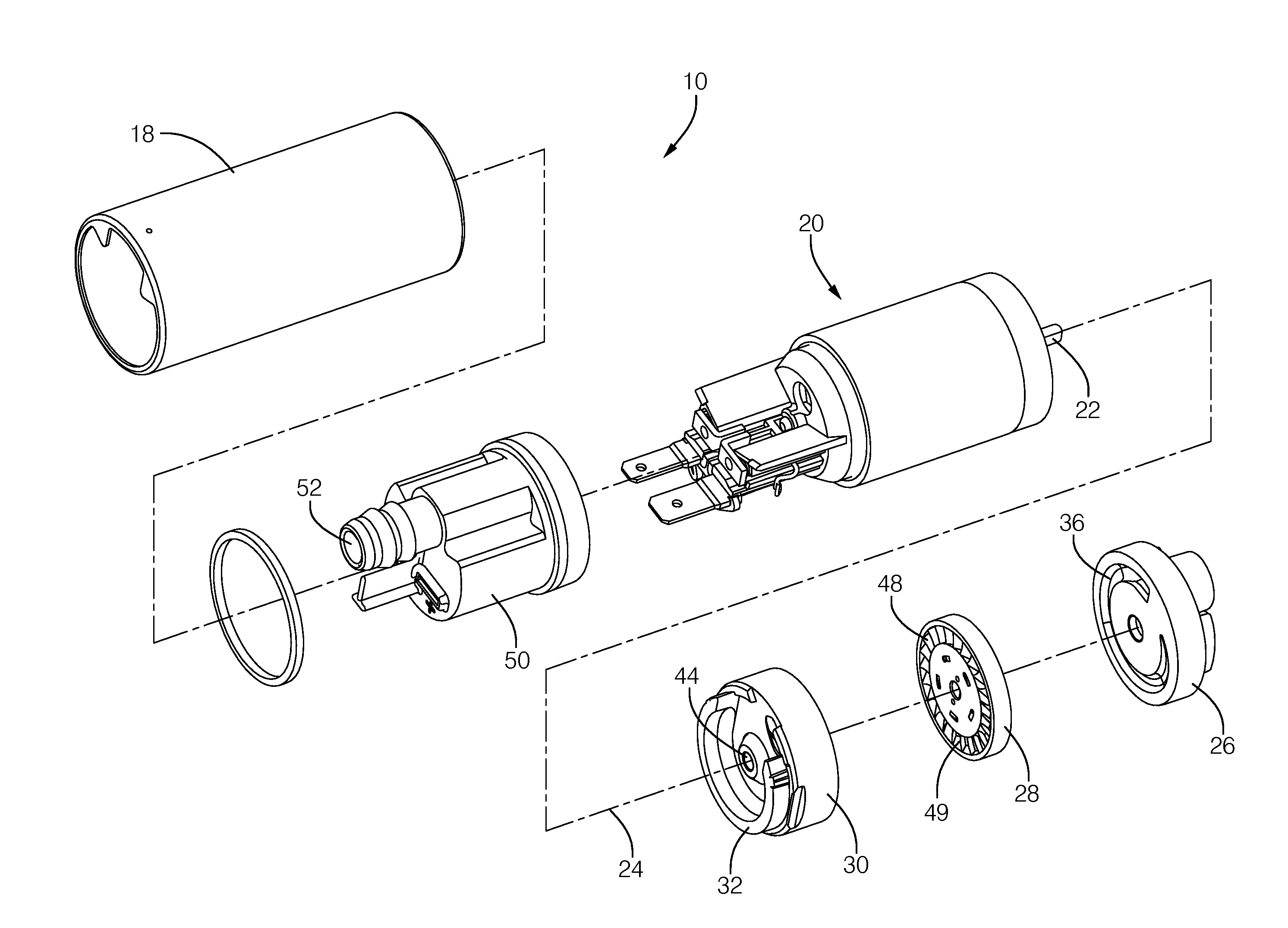
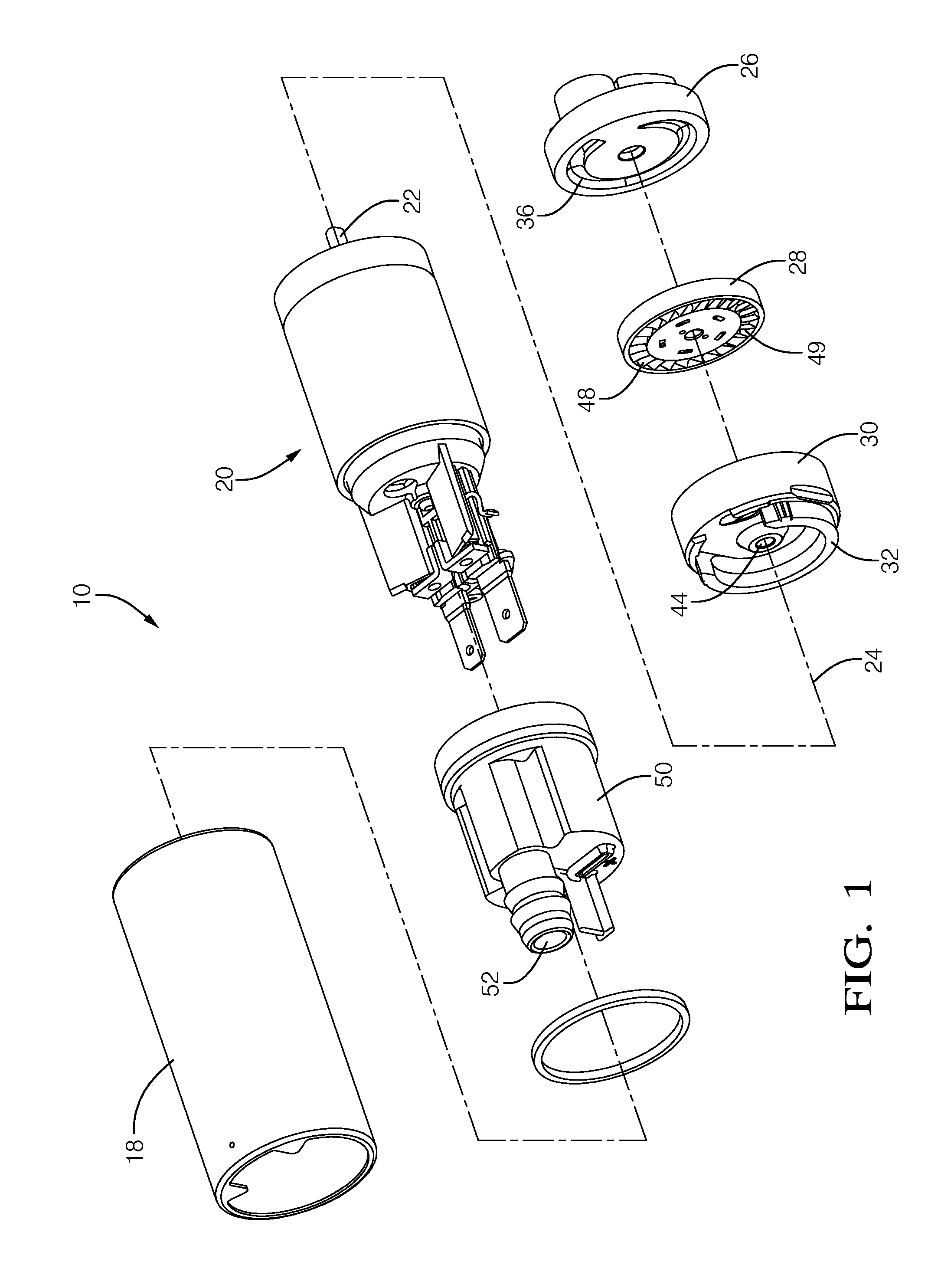
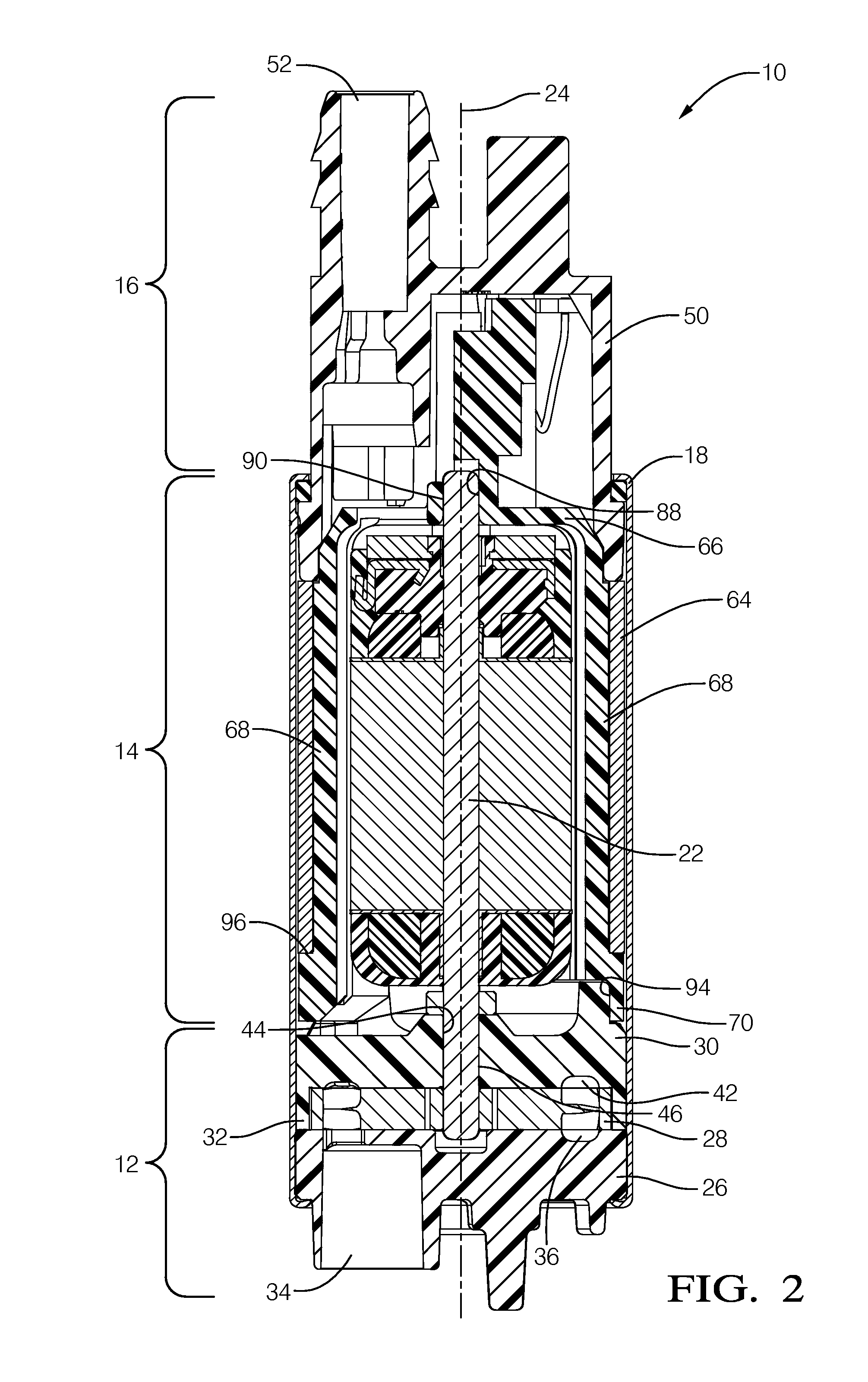
[0011]Reference will be made to FIGS. 1 and 2 which are an exploded isometric view and an axial cross-sectional view respectively of a fluid pump illustrated as fuel pump 10 for pumping liquid fuel, for example gasoline or diesel fuel, from a fuel tank (not shown) to an internal combustion engine (not shown). While the fluid pump is illustrated as fuel pump 10, it should be understood that the invention is not to be limited to a fuel pump, but could also be applied to fluid pumps for pumping fluids other than fuel. Fuel pump 10 generally includes a pump section 12 at one end, a motor section 14 adjacent to pump section 12, and an outlet section 16 adjacent to motor section 14 at the end of fuel pump 10 opposite pump section 12. A housing 18 of fuel pump 10 retains pump section 12, motor section 14 and outlet section 16 together. Fuel enters fuel pump 10 at pump section 12, a portion of which is rotated by motor section 14 as will be described in more detail later, and is pumped past...


PUM


Abstract

A fluid pump includes an inlet for introducing fluid into the fluid pump and an outlet for discharging fluid from the fluid pump. The fluid pump also includes a motor having a shaft with an upper end and lower end that rotates about an axis. The fluid pump also includes a motor frame having a top section, a base section, and a plurality of legs that axially separate the top section and the base section. The fluid pump also includes a lower bushing for radially supporting the lower end of the shaft. The top section defines an upper bushing therein for radially supporting the upper end of the shaft and the base section maintains a coaxial relationship between the lower bushing and the upper bushing.

Description

TECHNICAL FIELD OF INVENTION[0001]The present invention relates to a fluid pump; more particularly to a fuel pump; and even more particularly to a fuel pump with an electric motor with a motor frame that defines an upper bushing and maintains a coaxial relationship of a lower bushing with the upper bushing.BACKGROUND OF INVENTION[0002]Fluid pumps, and more particularly fuel pumps for pumping fuel, for example, from a fuel tank of a motor vehicle to an internal combustion engine of the motor vehicle, are known. United States Patent Application Publication No. US 2010 / 0047090 A1 shows one type of fuel pump which includes an impeller. An inlet plate is disposed adjacent to one face of the impeller and an outlet plate is disposed adjacent to the face of the impeller that is opposite the inlet plate. An electric motor of the fuel pump includes a shaft which is coupled to the impeller. One end of the shaft is supported radially by a lower bushing formed integrally with the outlet plate wh...

Claims


Application Information

Patent Timeline
IPC IPC(8): F04D13/06F04D29/04
CPCF04D29/04F04D13/06F04D5/002F04D29/046F04D29/628H02K1/17H02K5/148H02K5/15H02K5/1672H02K23/04
Inventor HERRERA, DANIELFISCHER, JOHN G.ASLAM, MOHAMMEDGONZALEZ, GUSTAVO
Owner DELPHI TECH IP LTD
Why Eureka
Try Eureka