Derailment-Preventing And Rerailing Safety Device For A Guide Unit Having Rollers Rolling On A Guide Rail

a safety device and guide rail technology, applied in the direction of steering controls, non-vehicle mounted steering controls, railway auxiliary equipment, etc., can solve the problems of relatively weak dynamic retention from detachment, detachment can occur, and the guide unit has rollers rolling on the guide rail, so as to facilitate disassembly and access, maintenance operations are thus much quicker and easier, and the effect of easy disassembly

Inactive Publication Date: 2014-11-13
NEWTL
View PDF20 Cites 3 Cited by
  • Summary
  • Abstract
  • Description
  • Claims
  • Application Information

AI Technical Summary

Benefits of technology

[0042]According to another advantage of the invention, thanks to the pivoting nature of the inclined flaps, the anti-extraction safety system is very easily dismountable, or is at least retractable, which provides very easy to access the parts of the guidance system located behind, notably including the inclined rollers, of which the tires must be replaced regularly.
[0043]Maintenance operations are thus much quicker and easier than with anti-extraction systems of prior art.

Problems solved by technology

While such a system is sufficient under normal circumstances, there are exceptional cases where a force exceeding the downward force is exerted in the opposite direction to the guidance system.
The guide rollers lift away from the guide rail and, when the vehicle moves forward, derailment can occur.
In effect, due to exposure to weather and the ambient environment of the guide track, it commonly occurs that the guide rail and / or its lateral grooves become locally encumbered or obstructed by matter of all kinds, vegetation, ice, snow, stones or other foreign objects deposited by accident, vandalism or whatever cause, thereafter constituting an obstacle to the passage of the guide roller(s), giving rise to their lifting and disengagement from the rail.
The lifting of the guide rollers and the ensuing detachment of the guidance system from the guidance area of the rail constitute an unacceptable hazard giving rise to major problems, notably derailment of the guidance system and, subsequently, the vehicle's exit from its trajectory.
However, because these flanges rotate with the guide rollers when the vehicle moves forward, their dynamic retention from detachment is relatively weak, due to a meshing phenomenon that occurs when the flange comes to bear against the side of the rail under the effect of a lateral force.
Furthermore, the system according to prior art provides no means of re-engagement in the event of disengagement of the guidance system from the guide rail.
Such a situation can occur, for example, when the head of the guide rail is damaged locally, or when the guide rail is worn, defective or intermittently missing on the vehicle's route.
The fixed fairing parts of the anti-extraction system, which are subject to very strong forces and stresses at their lower extension, in the event of strong vertical force, can also be worn, distorted or twisted.
In this case, when an exceptional obstacle such as a stone, debris or ice, is encountered under the wheels of the vehicle or in the gaps beside the guide rail, the vertical force exerted on the guidance system can then cause it to disengage from the guide rail.
In this situation, the anti-extraction system of prior art has no means of automatic re-engagement around the guide rail.
The guidance system can then no longer fulfill its function.
As a consequence of the vehicle no longer being guided, there is a major risk of an accident.

Method used


Image

  • Derailment-Preventing And Rerailing Safety Device For A Guide Unit Having Rollers Rolling On A Guide Rail
  • Derailment-Preventing And Rerailing Safety Device For A Guide Unit Having Rollers Rolling On A Guide Rail
  • Derailment-Preventing And Rerailing Safety Device For A Guide Unit Having Rollers Rolling On A Guide Rail

Examples


Embodiment Construction

[0060]The anti-extraction safety system according to the invention herein will now be described in detail, with reference to FIGS. 1 to 34. Equivalent items in the various figures are assigned the same reference numbers.

[0061]Further on in this description, the concepts of top and bottom, lower and upper, etc., are defined in accordance with the orientation adopted in the various Figures.

[0062]Similarly, front and rear are defined in accordance with the direction of travel of the vehicle.

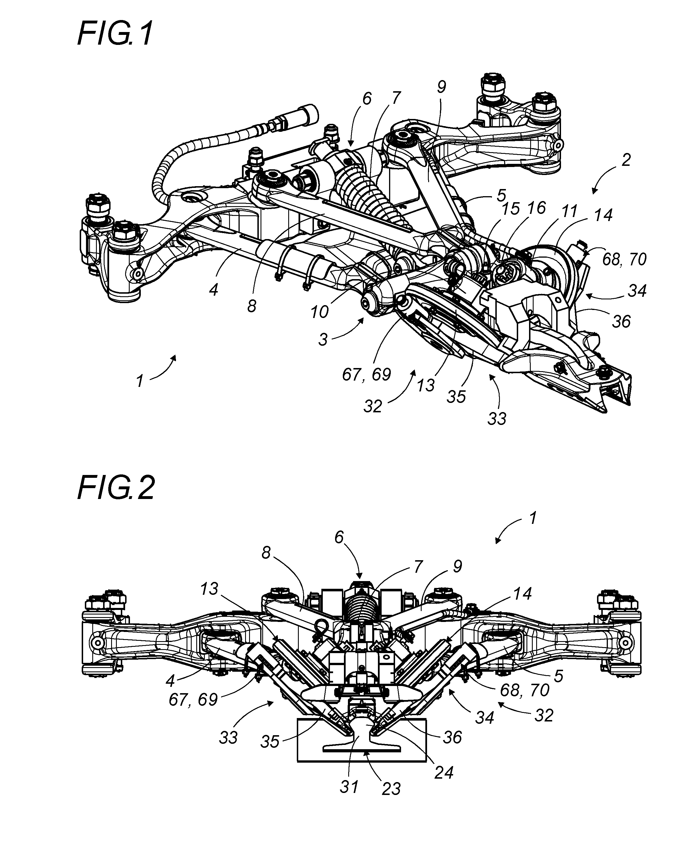
[0063]The anti-extraction safety system according to the invention can be implemented, for example, for a guidance system (1) as shown in FIG. 1.

[0064]There is a guidance head (2) pivotally mounted on a pivoting mounting (3), which itself is mounted on the vehicle by means of two pivoting arms (4) and (5), and a connection (6) with a downward resilient force, for example, by means of a spring (7), or a piston, or by means of simple gravity-driven return. This mobile assembly bears the guidance head ...


PUM


Abstract

The anti-extraction safety system incorporates, on each side, one side component which does not rotate with the corresponding roller, that incorporates at least one inclined flap articulated to pivot between a lowered position wherein its lower part extends under the rail head, and a raised position in which its lower part is laterally distanced from the rail. The pivot axis of the flap is inclined upwards and is located in the rear part of the flap, above the lower part in the lowered position. This flap is subjected to a downward return force which maintains it in the lowered position, but which allows it to pivot to the raised position when an upward force greater than the return force, is applied on its lower part.

Description

FIELD OF THE INVENTION[0001]The present invention concerns an anti-extraction safety system with re-engagement, for a system of guidance of a road vehicle guided by one or more rollers rolling on a guide rail, on the ground, for example.BACKGROUND OF THE INVENTION[0002]Advantageously, when the guidance system accidentally disengages from the guide rail, the operation of the anti-extraction safety system according to the invention then commences a phase of automatic re-engagement around the upper part of the guide rail, subsequent to its downward force, and the subsequent opening of the holding parts for their re-engagement around the guide rail, to provide the anti-extraction safety function.[0003]The invention is appropriate more particularly, but not exclusively, for urban public transport vehicles guided along a guide rail by means of a set of guide rollers.[0004]To ensure their guidance, guided public transport vehicles of this type incorporate a guidance system which continuous...

Claims


Application Information

Patent Timeline
Patent Type & Authority Applications(United States)
IPC IPC(8): B61F9/00B62D1/26
CPCB61F9/00B62D1/265
Inventor ANDRE, JEAN-LUC
Owner NEWTL
Why Eureka
Try Eureka