Electronic cigarette connection base and electronic cigarette atomization device

a technology of electronic cigarettes and connection bases, which is applied in the direction of tobacco pipes, tobacco, food science, etc., can solve the problems of low production efficiency of electronic cigarettes and bad sealing effect of electronic cigarettes, and achieve high product rate, good sealing effect, and simple assembly process

Inactive Publication Date: 2014-11-13
KIMREE HI TECH
View PDF3 Cites 51 Cited by
  • Summary
  • Abstract
  • Description
  • Claims
  • Application Information

AI Technical Summary

Benefits of technology

[0023]When implementing the electronic cigarette connection base and the electronic cigarette atomization device of the present invention, users do not need to re-design the connection base and make a new type of mould. When the filling groove is defined in the outer wall of the connection base and glue is filled therein, a good sealing effect can be achieved. The smoke oil in the oil storage cotton can be prevented from flowing into the battery device. The whole assembly process is simple, and the good products rate is high. Furthermore, the present invention can be used in existing connection bases, and achieve higher applicability.

Problems solved by technology

However, in the aforementioned assembly method, the electronic cigarette may need to make a new type of mould, an assembly process of the electronic cigarette is complicated, a production efficiency of the electronic cigarette is low, and a sealing effect of the electronic cigarette is bad.

Method used


Image

  • Electronic cigarette connection base and electronic cigarette atomization device
  • Electronic cigarette connection base and electronic cigarette atomization device
  • Electronic cigarette connection base and electronic cigarette atomization device

Examples


first embodiment

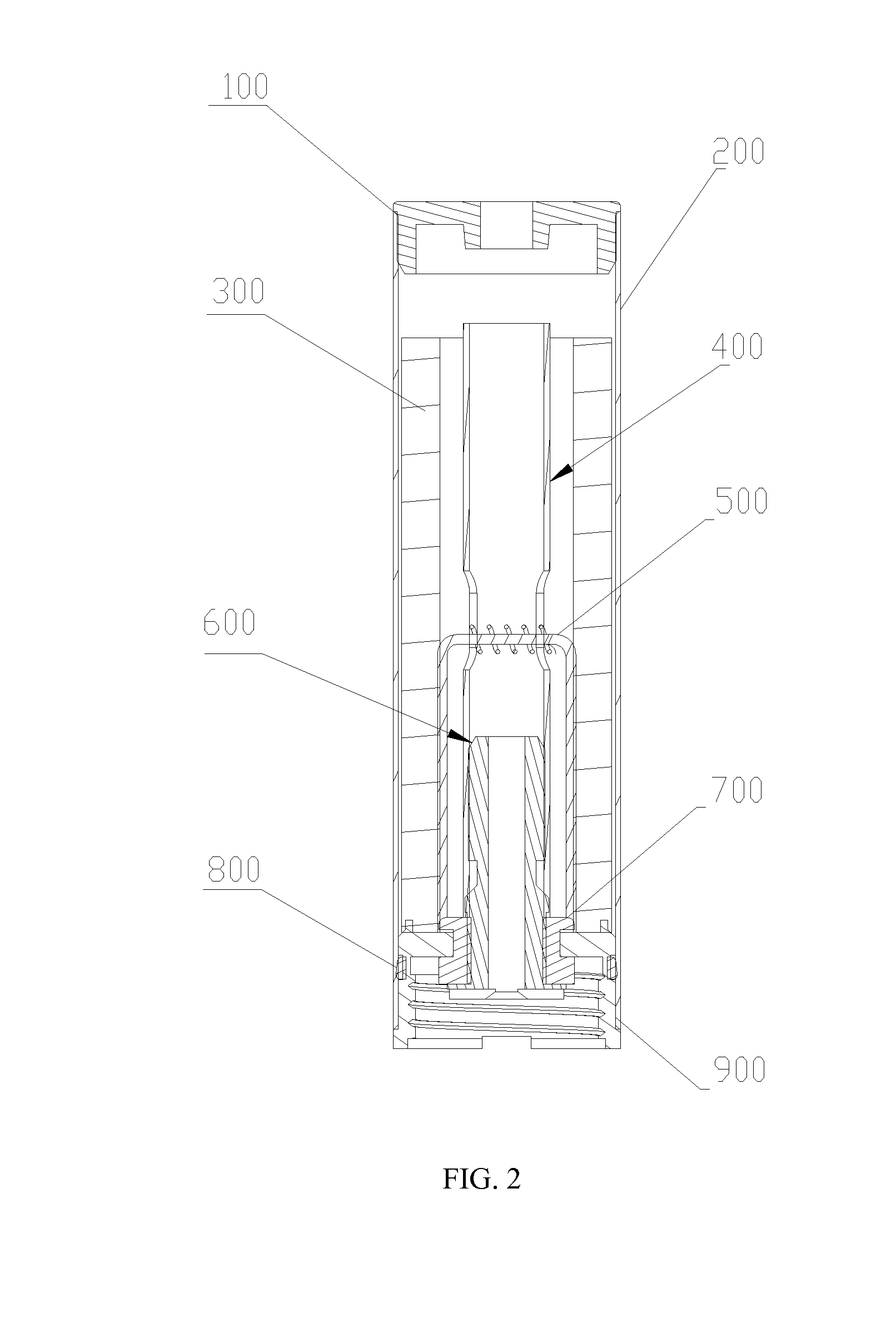
[0038]FIGS. 4-6 illustrate the present invention. Wherein, a connection base 900 comprises a top cover 903, a side wall 902 is formed around an edge of the top cover 903; the side wall 902 defines a filling groove around an outer surface of the side wall 902; and the filling groove 901 is filled with seal filler, for example, adhesive, such as different kinds of suitable glue. After filled with glue, the connection base 900 is embedded from the bottom of an atomization outer sleeve 200, and the outside of the side wall 902 of the connection base 900 is in tight contact with the atomization outer sleeve 200. In order to make the connection base 900 be in tight contact with the atomization outer sleeve 200, diameters of the connection base 900 and the atomization outer sleeve 200 should match with each other, and a complete electronic cigarette atomization device is formed in the way of interference fit or engagement. Additionally, the connection base 900 is chamfered, so that the con...

second embodiment

[0041]In the present invention, the filling groove 901 of the connection base 900 may be in other shapes. For example, in the present invention as shown in FIG. 7, the filling groove 901 includes straight line grooves which are perpendicular to the top cover (i.e., positioned along an axial direction of the periphery surface of the side wall of the connection base). Every two adjacent ones of these straight line grooves are parallel to each other and are separated with a certain distance. When the filling groove 901 is filled with glue and replaces the connection base 900 shown in FIG. 4 and FIG. 6, the sealing for the oil storage cotton 300 can also be achieve.

[0042]Two kinds of the filling grooves mentioned above have different advantages: in the first embodiment, the annular filling groove is corresponding to the inner wall of the whole atomization outer sleeve 200, therefore, the sealing effect is better; in the second embodiment, the longitudinal straight line filling groove ca...


PUM


Abstract

An electronic cigarette connection base and an electronic cigarette atomization device are provided; the connection base comprises a top cover; a side wall formed around an edge of the top cover; the side wall defining a filling groove around an outer surface of the side wall; and the filling groove filled with seal filler.

Description

CROSS-REFERENCE TO RELATED APPLICATIONS[0001]This application is a continuation of International Patent Application No. PCT / CN2013 / 075330, with an international filing date of May 8, 2013, designating the United States, now pending. The contents of these specifications are incorporated herein by reference.TECHNICAL FIELD[0002]The present invention relates to the field of electrical cigarette technology, and more particularly, relates to an electronic cigarette connection base and an electronic cigarette atomization device.BACKGROUND[0003]An electronic cigarette is an electronic product that uses heating wires to heat and atomize tobacco juice, and is configured to provide a kind of substitute of cigarettes for smokers. Heated tobacco juice becomes smoke, flows through a breather tube, and flows out of the electronic cigarette from an opening of a nozzle cover. As shown in FIGS. 1-3, an electronic cigarette generally comprises an atomization device (1) and a battery rod device (2), a...

Claims


Application Information

Patent Timeline
Patent Type & Authority Applications(United States)
IPC IPC(8): A24F47/00A24F40/10A24F40/40
CPCA24F47/008A24F40/10A24F40/40
Inventor LIU, QIUMING
Owner KIMREE HI TECH
Why Eureka
Try Eureka