
Linear mr-brake as a high force and low off-state friction actuator

a technology of linear mr-brakes and actuators, which is applied in the direction of shock absorbers, mechanical equipment, vibration suppression adjustments, etc., can solve the problems of large off-state force which is uncontrollable, large design changes, and undesirable force in many applications, so as to reduce reduce the off-state force. , the effect of reducing the size of the brak

Active Publication Date: 2014-11-13
WASHINGTON STATE UNIVERSITY
View PDF6 Cites 2 Cited by
  • Summary
  • Abstract
  • Description
  • Claims
  • Application Information

AI Technical Summary

Benefits of technology

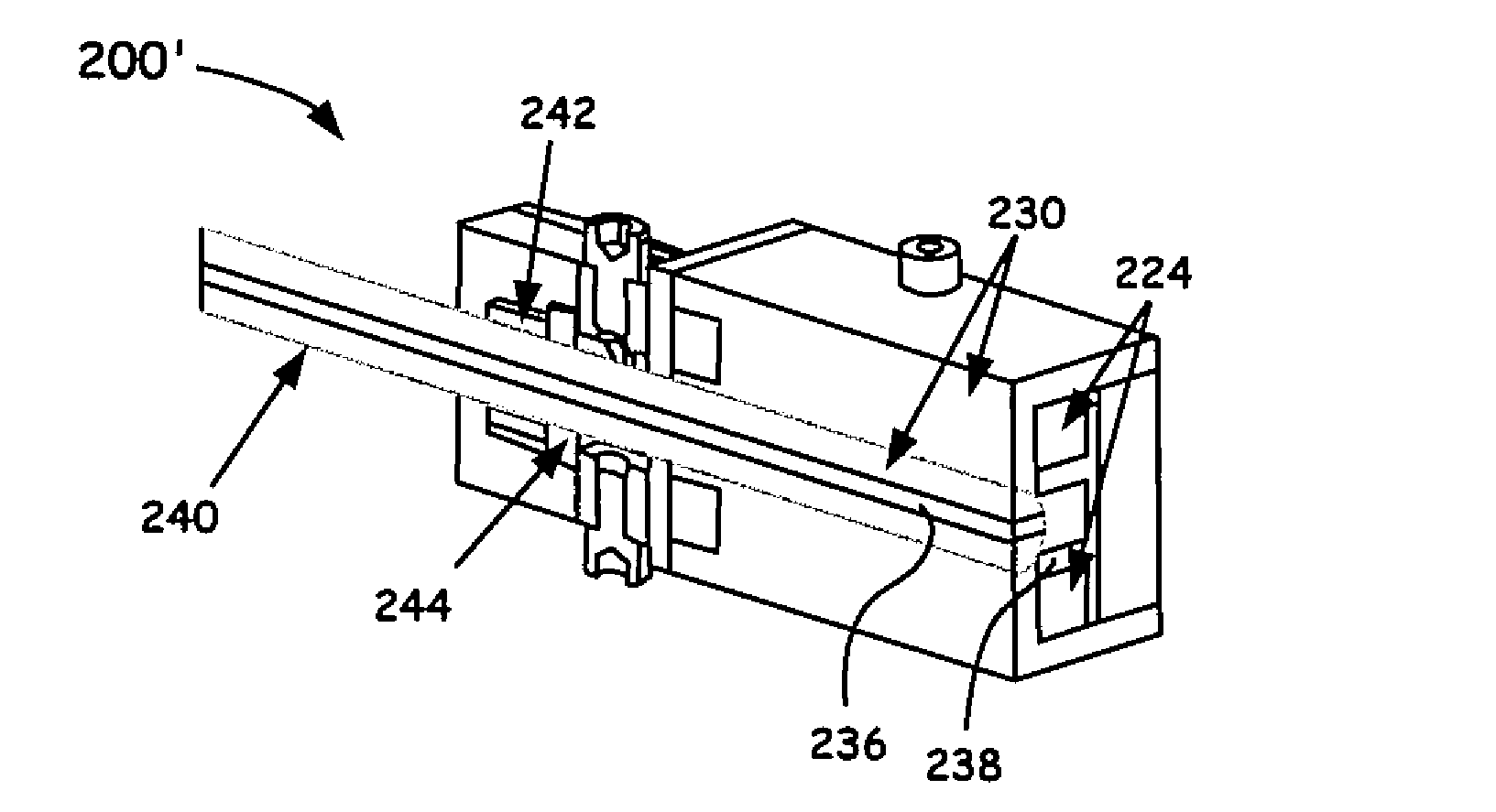
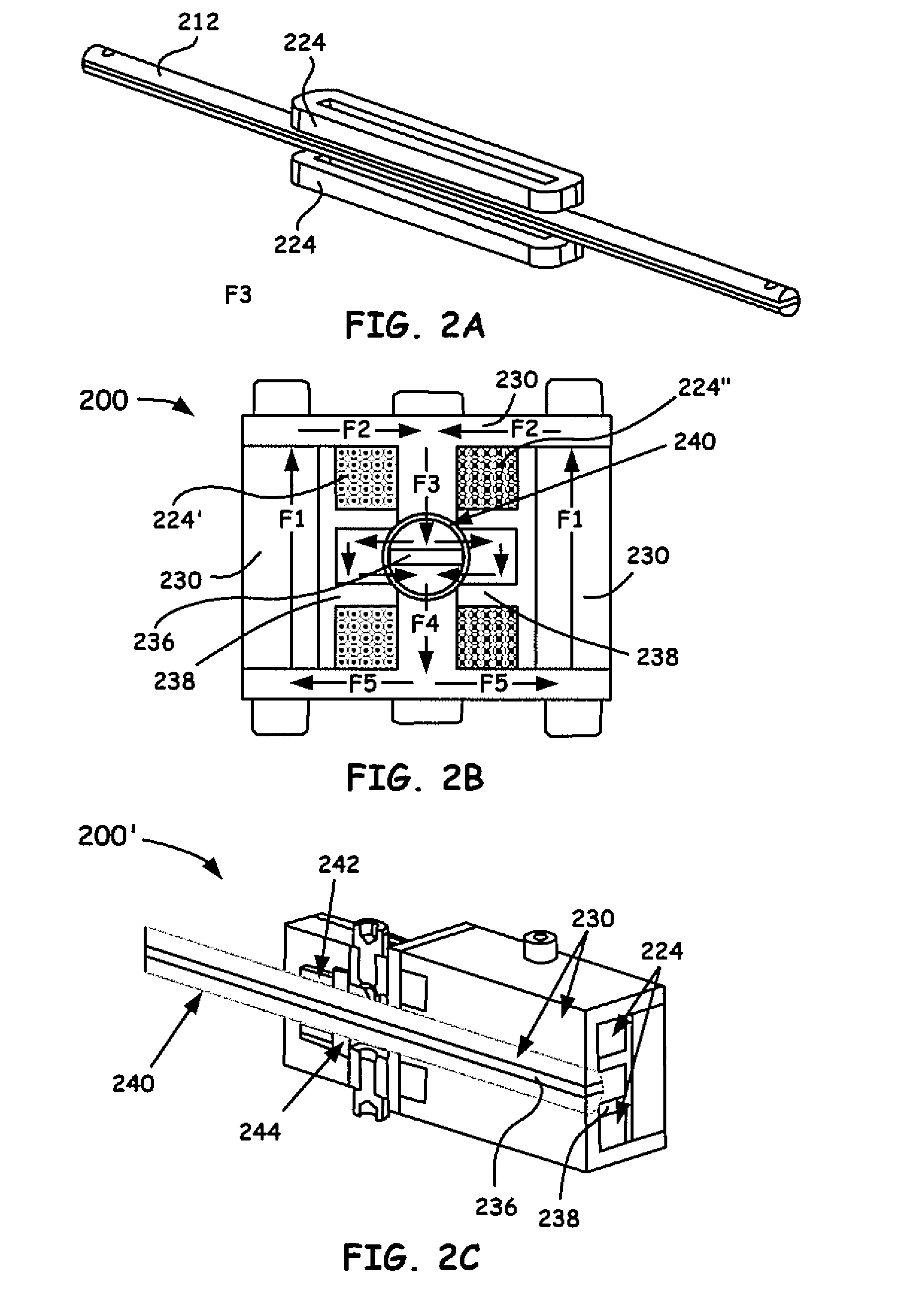
This patent is about a new type of brake that is compact and has a smooth motion. It uses a special method called serpentine flux path that increases the strength of the brake. This method involves inducing a magnetic flux and using a rod and housing with conductive and non-conductive materials to create multiple paths for the flux to flow through. By multiplexing the flux through the MR fluid, the brake can provide smooth control without being affected by friction. This design allows for a smaller and more efficient brake that can be controlled using less energy.

Problems solved by technology

All of these options lead to bulkier designs.
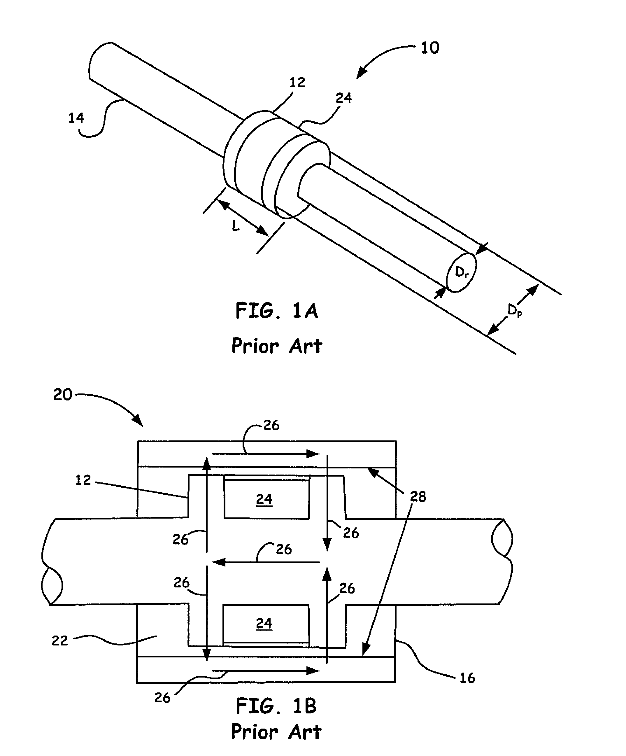
This leads to a significant off-state force which is uncontrollable and is in addition to that what the actuator (i.e., the housing arrangement discussion for FIG. 1B) applies even when the input current is turned off.
Such a force is undesirable in many applications, especially in haptics.
For example, such an undesirable off-state force (as coupled to a haptic interface that implements such actuators), keeps applying forces on the user's hand even when the user is not interacting with objects in a virtual simulation environment, hence reducing the realism of the interaction.

Method used


Image

  • Linear mr-brake as a high force and low off-state friction actuator
  • Linear mr-brake as a high force and low off-state friction actuator
  • Linear mr-brake as a high force and low off-state friction actuator

Examples


Embodiment Construction

[0037]In the description of the invention herein, it is understood that a word appearing in the singular encompasses its plural counterpart, and a word appearing in the plural encompasses its singular counterpart, unless implicitly or explicitly understood or stated otherwise. Furthermore, it is understood that for any given component or embodiment described herein, any of the possible candidates or alternatives listed for that component may generally be used individually or in combination with one another, unless implicitly or explicitly understood or stated otherwise. Moreover, it is to be appreciated that the figures, as shown herein, are not necessarily drawn to scale, wherein some of the elements may be drawn merely for clarity of the invention. Also, reference numerals may be repeated among the various figures to show corresponding or analogous elements. Additionally, it will be understood that any list of such candidates or alternatives is merely illustrative, not limiting, u...


PUM


Abstract

A novel method and apparatus is introduced to provide a new and robust alternative design for linear magnetorheological (MR) brakes, i.e. MR-brakes. The novel embodiments herein combines a serpentine flux path concept to eliminate conventional piston-cylinder arrangements and as a beneficial result when coupled with the linear brake embodiment disclosed herein, significantly reduce off-state friction and facilitates such devices to provide longer stroke length (i.e., infinite stroke lengths) beyond that as provided in conventional systems. The present linear brake embodiments disclosed herein thus provides, for example, for a ratio of the off-state friction force to the maximum force output at about 3% compared to 10% up to about 27% for similar conventional / commercial brake mechanisms. At the same time, the compactness is beneficially improved be being about half the size of a commercially available product.http: / / en.wikipedia.org / wiki / File:Paul_Patent_2939952_Fig5.gif

Description

CROSS-REFERENCE TO RELATED APPLICATIONS[0001]The present application claims under 35 U.S.C. §119, the priority benefit of U.S. Provisional Application No. 61 / 811,236, filed Apr. 12, 2013, entitled: “Linear MR-Brake with Serpentine Flux Path as A High Force and Low Off-State Friction Actuator for Haptics.” The disclosure of the foregoing application is incorporated herein by reference in its entirety.BACKGROUND OF THE INVENTION[0002]1. Field of the Invention[0003]The present invention relates to the field of brakes, dampers, actuators, resistance devices and motion control devices. More particularly, the present invention relates to devices employing a magnetic serpentine flux path and a responsive material for controlling torque / force in linear (non-piston-cylinder) configured braking systems.[0004]2. Discussion of the Related Art[0005]Controllable materials (e.g., fluids, powders, etc.), as utilized herein, exhibit a change in their rheological behavior (mainly their apparent visco...

Claims


Application Information

Patent Timeline
IPC IPC(8): F16D57/00
CPCF16D57/002F16D63/008F16F9/535
Inventor GUROCAK, HAKANALKAN, MUSTAFA SAIT
Owner WASHINGTON STATE UNIVERSITY
Learn More