
Method of aerosolizing a liquid

a liquid aerosol and liquid technology, applied in the field of portable devices, can solve the problems of degrading the molecules, affecting the aerosolization effect, and the device which generates the liquid aerosol may not work well with the molecules of high molecular weight or at high concentration, so as to achieve the effect of reducing the leakage of gas

Active Publication Date: 2014-11-13
YEATES DONOVAN
View PDF9 Cites 2 Cited by
  • Summary
  • Abstract
  • Description
  • Claims
  • Application Information

AI Technical Summary

Benefits of technology

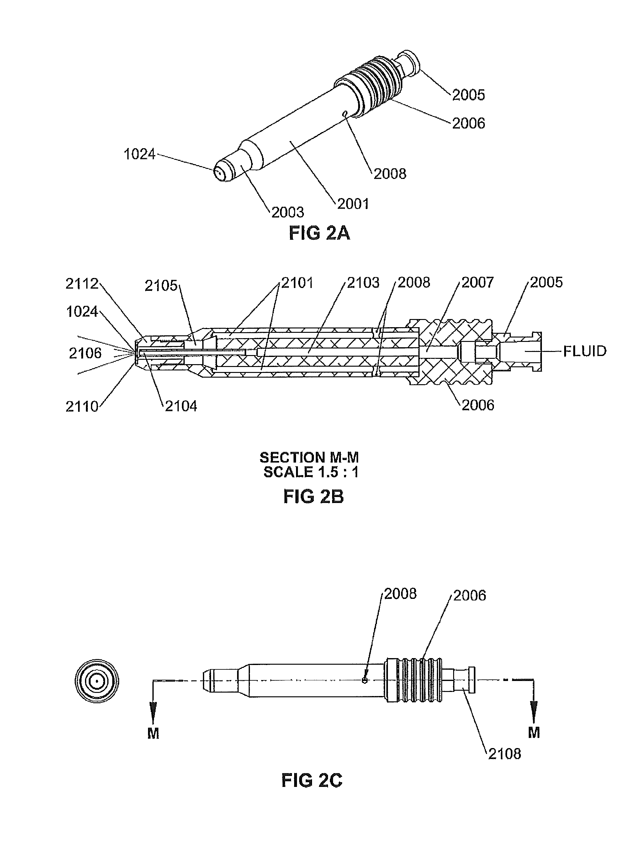
[0027]According to a preferred embodiment of the nozzle of the invention, the nozzle further comprises a cylindrical stem having an outer stem wall having an outer stem diameter; and an annulus having an annulus hole wall comprising an inner annulus diameter that is slightly larger than the outer stem diameter; wherein the cylindrical stem extends through the annulus hole and comprises the wettable cone-shaped gas exit channel; and the annular fluid exit port is formed by an annular gap between the annulus hole wall and the outer stem wall. Preferably, the diameter difference between the inner annulus diameter and the outer stem diameter is between 0.006 and 0.8 mm resulting in an annular gap width between the 0.003 and 0.4 mm. This allows benefiting from the capillary forces for the fluid transfer from the nozzle to in location where the fluid is aerosolized.
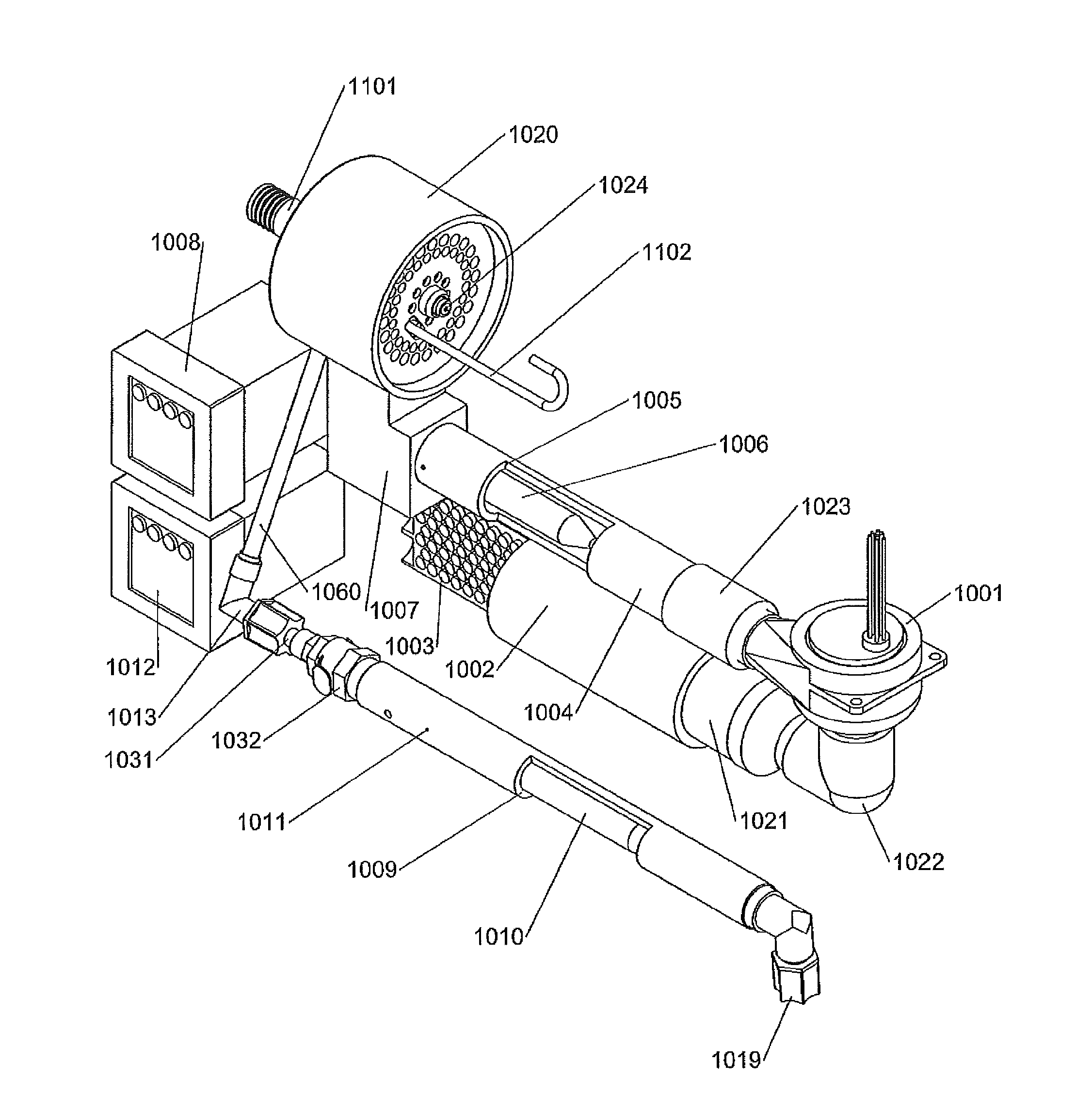
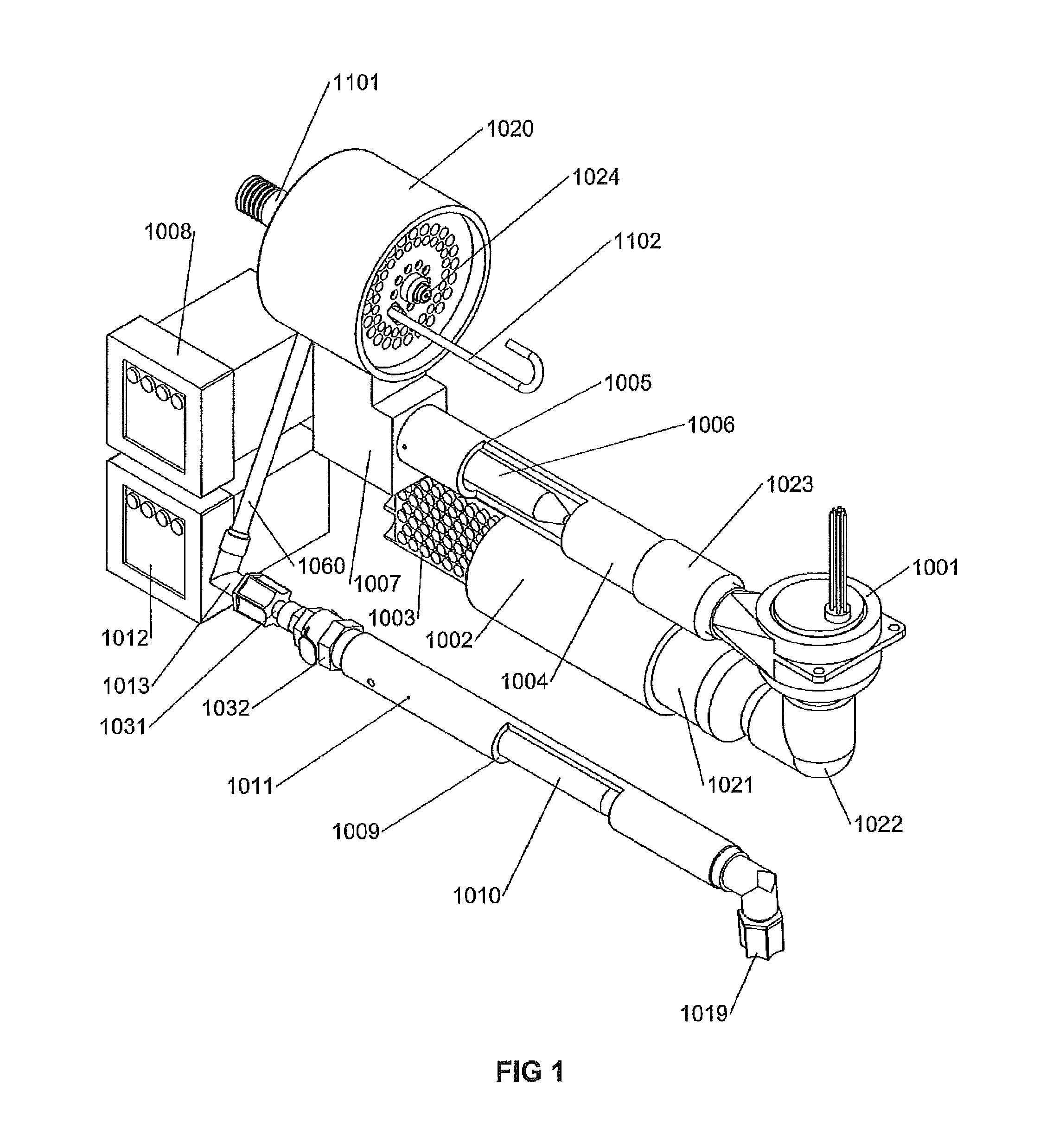
[0049]In this disclosure radial slits with large length / width ratios are described to minimize end effects and provide a clear path for the exhaust gas to exit. The use of multiple slit lengths achieves two objectives, a) to maximize the total cumulative length of the slits to minimize the pressure drop across the concentrator and b) to achieve relatively uniform flow at the exit of the evaporation chamber as well as concentrically relatively uniform across the concentrator.

Problems solved by technology

Many devices which generate liquid aerosols may not work well with molecules of high molecular weight or at high concentrations.
In addition, some of these devices may degrade the molecules during aerosolization.
These limitations, together with the need to reduce the use of fluorocarbons, have lead to the development of dry powder inhalers.
The use of excipients results in increased formulation costs, safety pharmacology costs and potential unwanted side effects.
a) The stored resultant dry particles must be stable and preferably resistant to high humidity.
b) They must be formulated with excipients such as to be easily dispersed
c) The size of the drug particles is generally smaller than that of the excipient particles when the two chemicals are in discrete form.
d) The maximum which can be inhaled is limited to the size of the capsule not the volume of the inhalation.
e) The spray dry process is likely 60% efficient and the delivery to the lungs by the dry power inhaler 30% efficient resulting in losses of some 80% of the active agent.
f) A rapid inhalation results in most of the powder in the capsule being aerosolized but results in high mouth and throat deposition. A slow inhalation can result in higher deep lung deposition but a low efficiency of aerosolization of the powder in the capsule. These issues lead to wide variability in the dose administered leading to both efficacy and safety concerns.
This and the above modifications reduce the overall power used by the device.
This potentially increases the pressure head required to accelerate the aerosol through the slits.
When concentric slits are used it is much more difficult to exhaust the gas than using the present compact design.

Method used


Image

  • Method of aerosolizing a liquid
  • Method of aerosolizing a liquid
  • Method of aerosolizing a liquid

Examples


examples

[0123]The flow resistance of the dilution heater was found to be 0.12, 0.3 and 0.5 inches of water at 100, 150 and 200 liters per minute, respectively. The flow resistance of the flow conditioner was determined to be 1 inch of water at 150 liters per minute and 1.8 inches of water at 200 liters per minutes. The flow resistance of the aerosol concentrator was determined to be less than 1 mm of water at all tested input flow rates below 300 liters / minute when the concentrator output flow rate was 40 liters per minute. The pressure inside the evaporation chamber was 0.3, 0.8, 1.4, 2.2 and 2.7 inches of water at chamber flow rates of 100, 150, 200, 250 and 300 liters / minute, respectively when the output flow rate of the concentrator was 40 liters / min.

[0124]A solution of 16% bovine serum albumin was fed to the nozzle using an infusion pump and aerosolized at 1 ml / minute. The nozzle pressure was 20 to 24 psi and the dilution gas flow 200 liters / minute. The resultant dry aerosol downstream...


PUM

PropertyMeasurementUnit
annular gap widthaaaaaaaaaa
angleaaaaaaaaaa

Abstract

A method of aerosolizing a liquid by generating an aerosol from a liquid fluid and a gas with a nozzle having a cone-shaped gas exit channel, the method including the method steps of: ejecting a nozzle gas jet through an orifice at the cone apex; generating a zone of low pressure by the ejected nozzle gas jet, the zone of low pressure augmenting a flow of liquid fluid in a direction from a nozzle cone base towards the orifice at the cone apex; and aerosolizing the liquid fluid at the aerosolizing perimeter where the liquid fluid that flows towards the orifice is sheared by the nozzle gas jet.

Description

CROSS-REFERENCE TO RELATED APPLICATIONS[0001]This application is a Continuation patent application of U.S. Ser. No. 12 / 890,302 filed Sep. 24, 2010 and published under the publication no. US-2011-0011899-A1 on Jan. 20, 2011, which is a Continuation-in-part patent application claiming the benefit of the U.S. non-provisional patent application Ser. No. 11 / 315,951 filed on Dec. 22, 2005 and published under the publication no. US-2007-0144514-A1 on Jun. 28, 2007 and issued as U.S. Pat. No. 7,802,569 on Sep. 28, 2010. These prior non-provisional patent application Ser. Nos. 11 / 315,951 and 12 / 890,302 are herewith incorporated in its entirety by reference.GOVERNMENT SUPPORT[0002]The present invention was made with U.S. Government support from the National Institutes of Health, National Heart, Lung, and Blood Institute, under grant No. HL78281. The U.S. Government has certain rights in this invention.BACKGROUND OF THE INVENTION[0003]The present disclosure relates to a compact portable device...

Claims


Application Information

Patent Timeline
Patent Type & Authority Applications(United States)
IPC IPC(8): B05B7/06
CPCB05B7/065A61M11/06A61M15/008A61M15/0086A61M2016/0036A61M2205/362A61M2205/368B01D45/08
Inventor YEATES, DONOVAN B.
Owner YEATES DONOVAN
Learn More