Compact, low flow resistance aerosol generator and method of operating the same

a generator and low flow resistance technology, applied in the field of compact portable devices, can solve the problems of degrading molecules, affecting the efficiency of aerosol generators, and many devices which generate liquid aerosols may not work well with molecules of high molecular weight or at high concentration, so as to achieve the effect of reducing gas leakag

Inactive Publication Date: 2013-09-26
YEATES DONOVAN B
View PDF0 Cites 4 Cited by
  • Summary
  • Abstract
  • Description
  • Claims
  • Application Information

AI Technical Summary

Benefits of technology

[0018]A fourth object of the present disclosure is to minimize leakage of gas and/or aerosol between the var

Problems solved by technology

Many devices which generate liquid aerosols may not work well with molecules of high molecular weight or at high concentrations.
In addition, some of these devices may degrade the molecules during aerosolization.
These limitations, together with the need to reduce the use of fluorocarbons, have lead to the development of dry powder inhalers.
The use of excipients results in increased formulation costs, safety pharmacology costs and potential unwanted side effects.
a) The stored resultant dry particles must be stable and preferably resistant to high humidity.
b) They must be formulated with excipients such as to be easily dispersed
c) The size of the drug particles is generally smaller than that of the excipient particles when the two chemicals are in discrete form.
d) The maximum which can be inhaled is limited to the size of the capsule not the vo

Method used


Image

  • Compact, low flow resistance aerosol generator and method of operating the same
  • Compact, low flow resistance aerosol generator and method of operating the same
  • Compact, low flow resistance aerosol generator and method of operating the same

Examples


examples

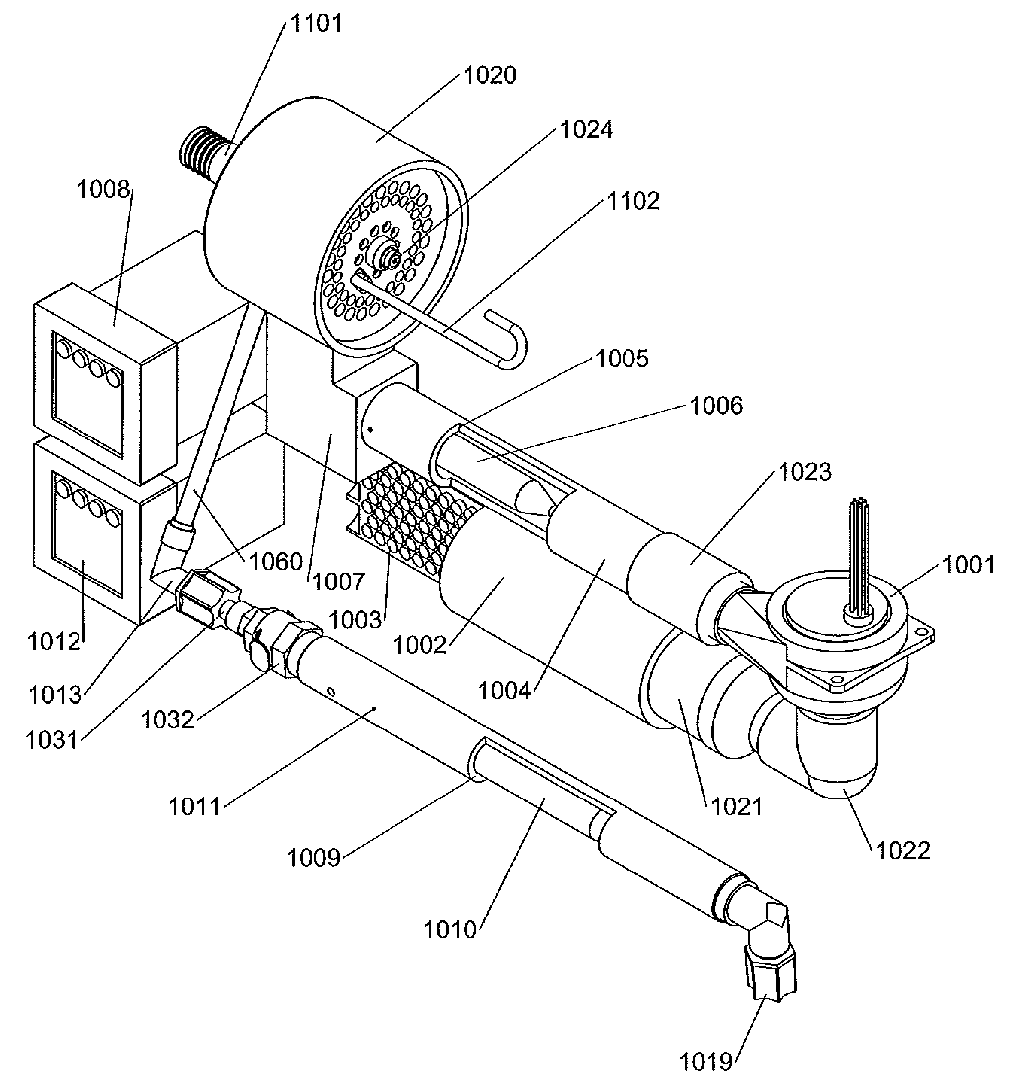
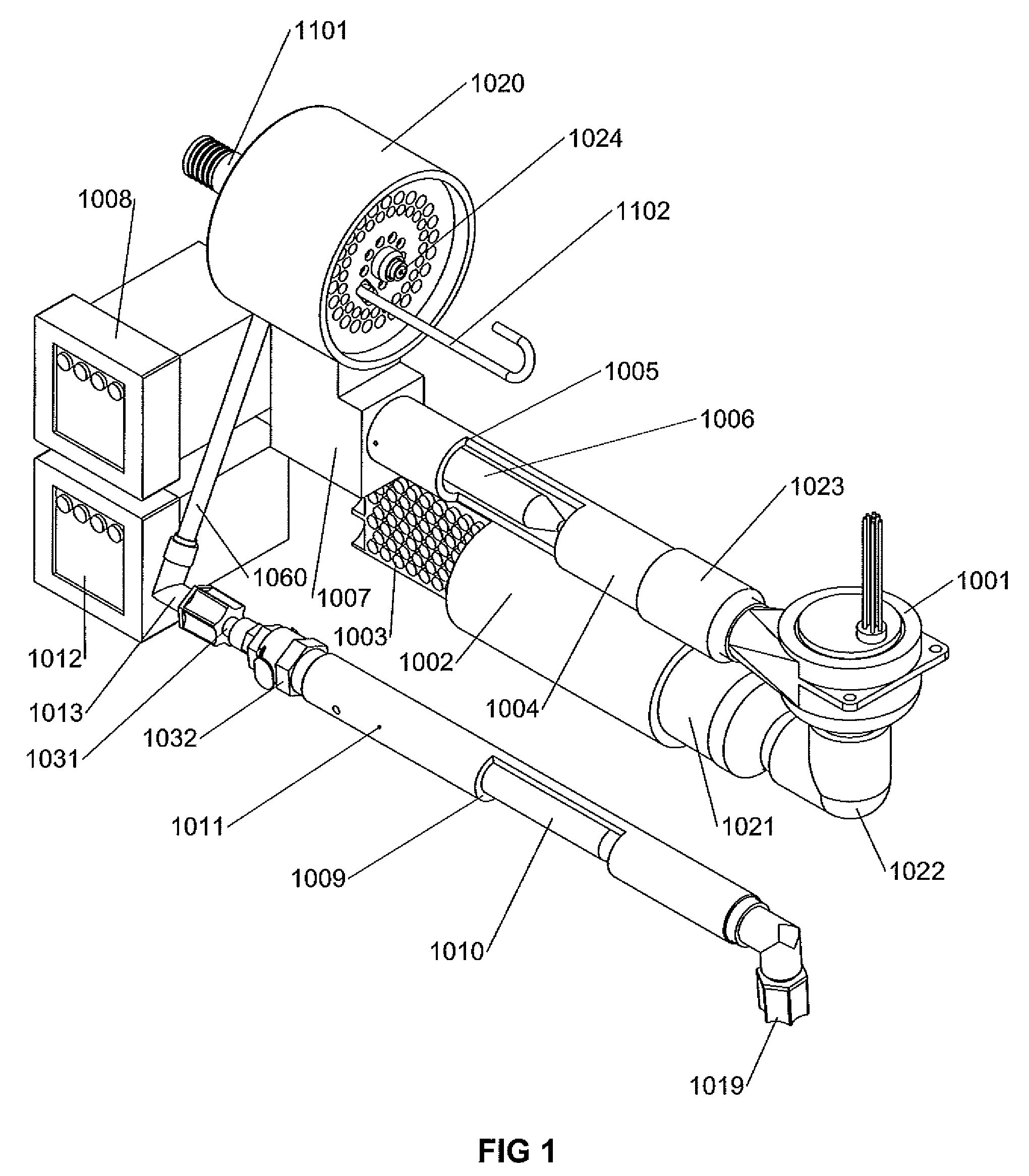
[0188]The flow resistance of the dilution heater was found to be 0.12, 0.3 and 0.5 inches of water at 100, 150 and 200 liters per minute, respectively. The flow resistance of the flow conditioner was determined to be 1 inch of water at 150 liters per minute and 1.8 inches of water at 200 liters per minutes. The flow resistance of the aerosol concentrator was determined to be less than 1 mm of water at all tested input flow rates below 300 liters / minute when the concentrator output flow rate was 40 liters per minute. The pressure inside the evaporation chamber was 0.3, 0.8, 1.4, 2.2 and 2.7 inches of water at chamber flow rates of 100, 150, 200, 250 and 300 liters / minute, respectively when the output flow rate of the concentrator was 40 liters / min.

[0189]A solution of 16% bovine serum albumin was fed to the nozzle using an infusion pump and aerosolized at 1 ml / minute. The nozzle pressure was 20 to 24 psi and the dilution gas flow 200 liters / minute. The resultant dry aerosol downstream...


PUM


Abstract

A method and an apparatus are described for generating a concentrated aerosol. A first heated volume flow of pressurized gas, a second volume flow of preheated dilution gas, and a third volume flow of fluid are provided. After creating a droplet aerosol from a solution, the aerosol solvent is quickly evaporated for creating a powder aerosol that then concentrated with a virtual impactor. The apparatus comprises a low flow resistance and achieves a high evaporation rate. The apparatus comprises a flow conditioner, nozzle, nozzle holder, and a concentrator.

Description

CROSS-REFERENCE TO RELATED APPLICATIONS[0001]This application is a Continuation-in-part patent application claiming the benefit of the U.S. non-provisional patent application Ser. No. 11 / 315,951 filed on Dec. 22, 2005 and published under the publication no. US-2007-0144514-A1 on Jun. 28, 2007. This prior non-provisional patent application Ser. No. 11 / 315,951 is herewith incorporated in its entirety by reference.GOVERNMENT SUPPORT[0002]The present invention was made with U.S. Government support from the National Institutes of Health, National Heart, Lung, and Blood Institute, under grant No. HL78281. The U.S. Government has certain rights in this invention.BACKGROUND OF THE INVENTION[0003]The present disclosure relates to a compact portable device for the generation of concentrated respirable dry particles from an aqueous solution or suspension.[0004]There is an ever increasing need to deliver large masses of biologics and other agents to the respiratory tract by aerosol. Many device...

Claims


Application Information

Patent Timeline
IPC IPC(8): B05B12/00
CPCA61M11/06A61M15/0086A61M16/0066A61M2016/0015A61M2016/0039A61M2202/062A61M11/003A61M2205/3372A61M2205/3653A61M2205/368A61M2206/14B05B12/00A61M2202/064A61M11/042
Inventor YEATES, DONOVAN B.
Owner YEATES DONOVAN B
Why Eureka
Try Eureka